Chapter3 Installation / 15
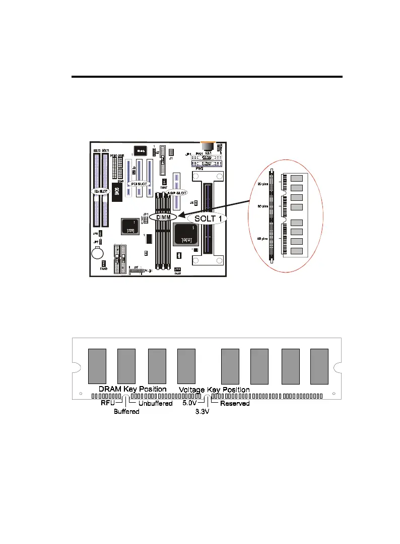
DIMM Memory Installation
Insert the module (s) as shown. Because the number pins are differ-
ent on either side of the breaks,the module will only fit in the ori-
entation as shown. SDRAM DIMM modules have different pin con-
tacts on each side and therefore have a higher pin density.
168 Pin DIMM Memory Socket
The Dual Inline Memory Module (DIMM) memory module must
be 3.3v Extended Data Output (EDO) DRAM or SDRAM. You can
identify the type of DIMM module by the illustration below:
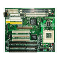
168 Pin DRAM DIMM Notch Key Definitions
The notch on the DIMM module will shift between left, center, or
right to identify the type and also to prevent the wrong type to be
inserted into the DIMM slot on the Mainboard. You must ask your
retailer for Specifications before purchasing.
Four clock signals are supported on this mainboard
JP8