28 / Chapter 3 Installation
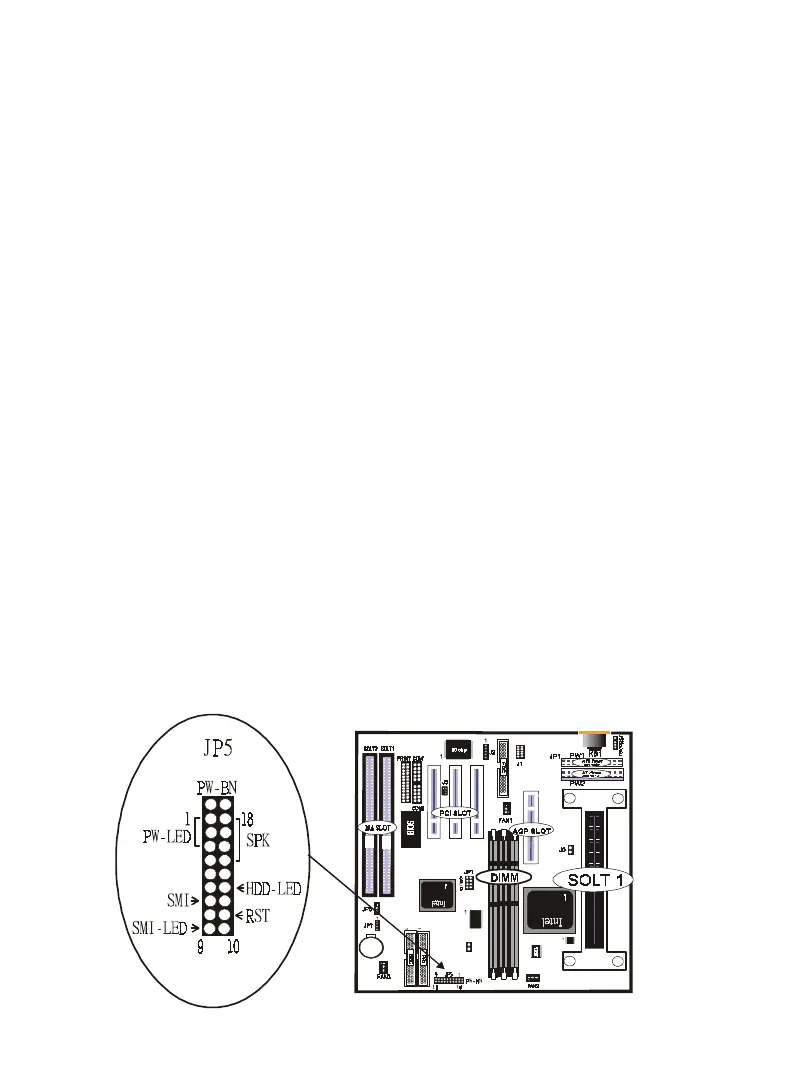
9. JP5
a. IDE activity LED (HD_LED)
This connector supplies power to the cabinet’s IDE activity LED.
Read and write activity by devices connected to the Primary or
Secondary IDE connectors will cause the LED to light up.
b. Power LED Lead (PW_LED)
The system power LED lights when the system’s power is on.
c. SMI Suspend Switch Lead (SMI)
This allows the user to manually place the system into a suspend
mode or “Green” mode where systematic activity will be in-
stantly decreased to save electricity and expand the life of cer-
tain components when the system is not in use. This 2-pin con-
nector (see the figure below) connects to the case-mounted sus-
pend switch. If you do not have a switch for the connector, you
may use the “Turbo Switch” since it does not have a function.
SMI is activated when it detects a short to open moment and
therefore leaving it shorted will not cause any problems. It may
require one or two pushes depending on the position of the
switch. Wake-up can be controlled by settings in the BIOS but
the keyboard will always allow wake-up (the SMI lead cannot
wake-up the system). If you want to use this connector,"Suspend
Switch" in the Power Management Setup of the BIOS SOFT-
WARE section should be on the default setting of Enable.
JP8