ACTentry A5 Operating and Installation Manual Rev 1.1
ACTentry A5 Entry Panel Installation
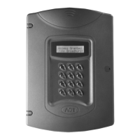
The ACTentry Entry Panel is made from 2 separate parts: a front unit and a base unit. The front
unit contains the speaker and keypad. The base unit contains the electronics, microphone and
connector blocks. The two units are interconnected via 2 flying leads, one for speaker (label 4)
and one for the keypad (label 6). Handle these connections with care when connecting or
disconnecting!
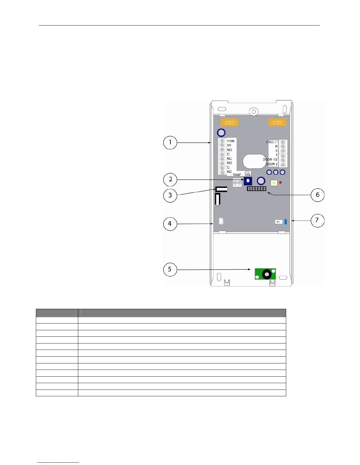
1.Connector Blocks
2.Volume potentiometer
3.Volt-Free Tamper
4.Speaker connector
5.Microphone
6.Keypad connector
7.Default Link LK1
Connector Description
+VIN +DC Voltage of 15V to 24V or 24Vac
0V 0 Volts
NO Normally Open Relay Contact
C Common Relay Contact
NC Normally Closed Relay Contact
TAMP Normally Closed Dry Contact (Volt Free). Normally closed in tamper conditions.
CALL / I Normally low output, + 15V signal to Intercom to ring when CALL button pressed
R Audio signal intput from Intercom
O 0 Volts
T Audio signal output to Intercom
DOOR1 / Z Normally 5V input, 0V signal from Intercom and Phone to open Door 1
DOOR 2 Normally 5V input, 0V signal from Intercom to open Door 2
7