ACTentry A5 Operating and Installation Manual Rev 1.1
ACTentry A5 Intercom Installation
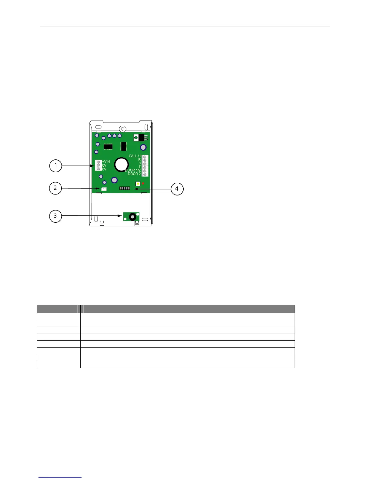
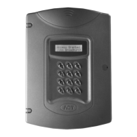
The ACTentry Intercom is made from 2 separate parts: a front unit and a base unit. The front unit
contains the speaker and keypad. The base unit contains the electronics, microphone and
connector blocks. The two units are interconnected via 2 flying leads, one for speaker (label 4)
and one for the keypad (label 6). Handle these connections with care when connecting or
disconnecting!
1.Connector Blocks
2.Speaker connector
3.Microphone
4.Keypad connector
Connector Description
+VIN +DC Voltage of 15V to 24V – Do not use AC.
0V 0 Volts
CALL / I Normally low input, + 15V signal to ring intercom
R Audio signal output to Entry Panel
O 0 Volts
T Audio signal input from Entry Panel
DOOR1 / Z Normally 5V output, 0V signal when Button 1 is pressed
DOOR 2 Normally 5V output, 0V signal when Button 2 pressed
8