Hardware Manual
9
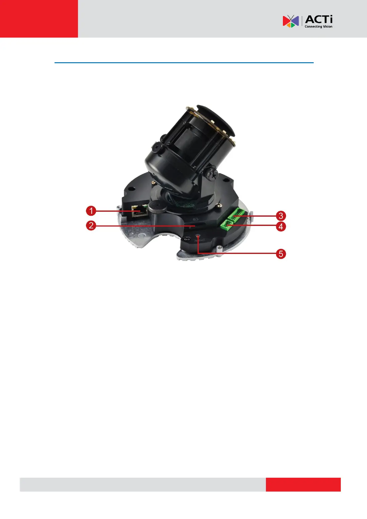
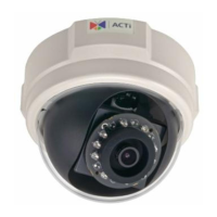
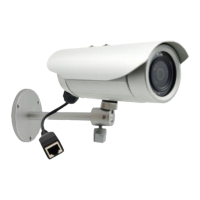
Physical Description
NOTE: The camera images on this documentation are for reference only. Actual camera may
slightly differ.
1) Ethernet Port
Connects to a network using an Ethernet cable.
2) Memory Card Slot
Insert a memory card into this slot for local recording purposes. See How to Install a
Memory Card on page 25 for more information.
NOTE: Supports microSDHC and microSDXC cards.
3) Digital Input / Output (DI/DO)
This connector connects to digital input or output devices, such as an alarm trigger, panic
button, etc. Digital Input (DI) and Digital Output (DO) devices are used in applications like
motion detection, event triggering, alarm notifications, etc. See Connecting the DI/DO
Devices (Optional) on page 14 for information on how to connect DI/DO devices to your
camera.