Hardware Manual
10
Physical Description
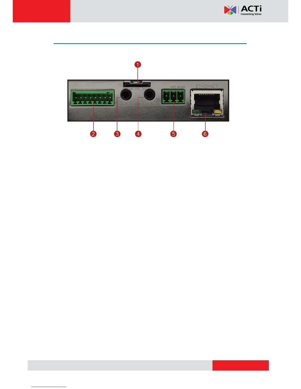
Connectors View
1) Memory Card Slot
Insert a memory card (not included) into the slot for local recording purposes.
NOTE: Supports microSDHC and microSDXC cards.
2) Digital Input / Output (DI/DO)
This connector connects to digital input or output devices, such as an alarm trigger, panic
button, etc. Digital Input (DI) and Digital Output (DO) devices are used in applications like
motion detection, event triggering, alarm notifications, etc. Please refer to Preparing the
DI/DO Connector on page 15 for information on how to connect DI/DO devices to your
camera.
3) Audio IN
This jack connects to an audio input device, such as a microphone with built-in amplifier.
NOTE: Make sure that the connected audio input device has a built-in amplifier. Connecting an
ordinary microphone will dwarf sounds and will result in inaudible recording.
4) Audio OUT
This jack connects to an audio output device, such as a speaker.
5) DC 12V Power Input
Connect DC power source to the terminal block. The wire with white dashed lines is the live wire,
which should connect to the 12V pin.
6) Ethernet Port
The Ethernet port connects to a network using a standard Ethernet cable.