Hardware Manual
15
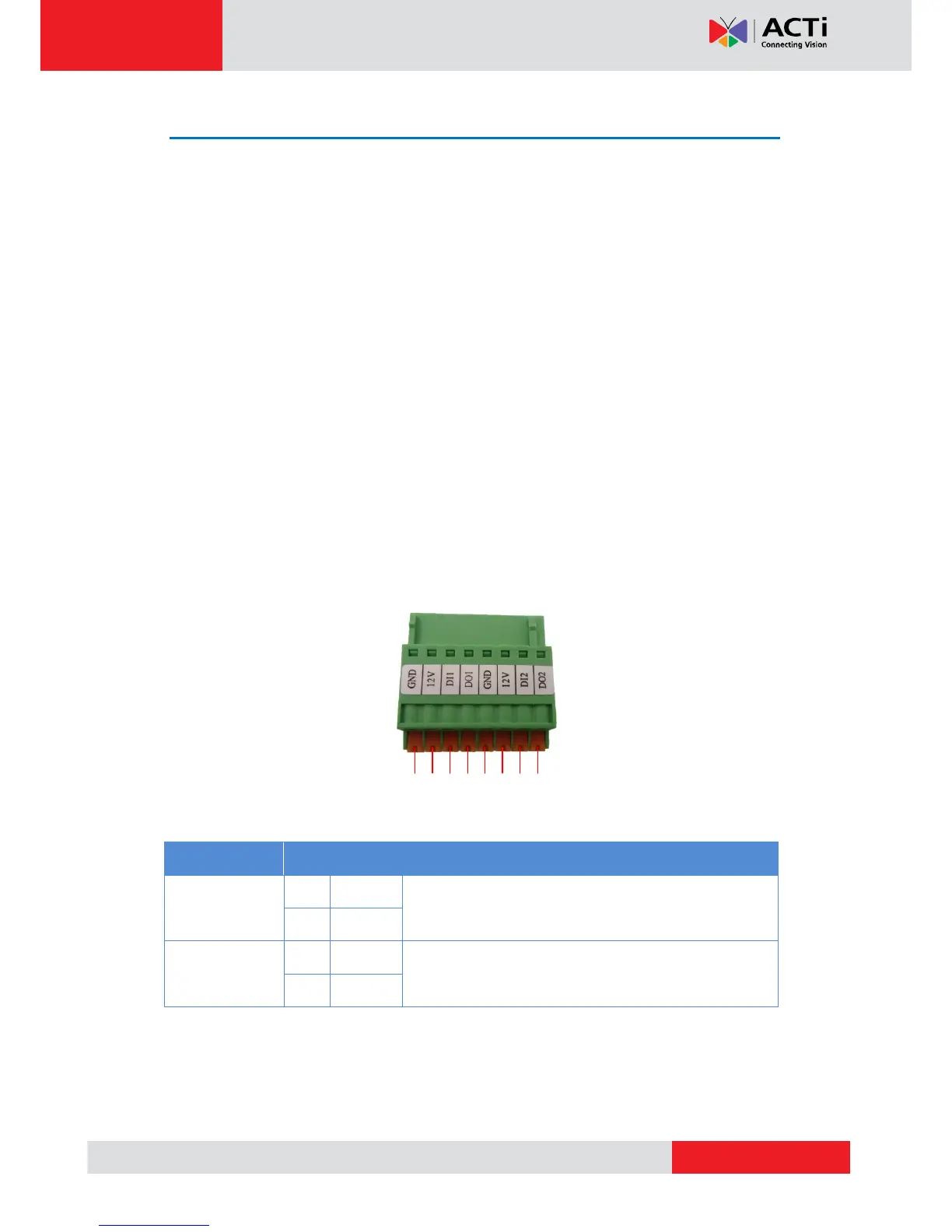
Preparing the DI/DO Connector
Depending on your surveillance needs, you may connect digital input or output devices to your
camera to trigger events or notifications.
Digital Input (DI) devices can be used to notify the camera about an activity in the camera site.
DI can be triggers of events. For example, you can connect a “panic button” to the camera; as
such when the panic button is pressed, the alarm signal will be sent through the camera. Other
common DI device applications are emergency button, smoke detector, passive infrared sensor,
etc.
Digital Output (DO) devices are external devices that are activated by the camera upon an
event inside the camera. For example, you can connect an “alarm horn” to the camera; as such
when an event occurs inside the camera (e.g. detected intruder), the alarm horn will sound.
Other common DO device applications are motion-triggered lights, electric fence, magnetic
door locks, etc.
You can connect up to two DI and two DO devices to your camera.
To connect input devices (DI), map the pins to one of the pin combinations below: