Installation and Commissioning Guide
Split Ducted ESP Digital
Installation and Commissioning Guide - Split Ducted ESP Digital Units
Doc. No.0525-077 Ver. 2 200129
31
2. Calculate the system super heat using the formula below:
Superheat = SLT - SST
3. If superheat is within the range (see charging table below), there is no need to add/remove refrigerant.
• If superheat is lower than minimum, it means that liquid refrigerant may be returning to compressor. It is
necessary to remove refrigerant or check EEV settings.
• If superheat is higher than maximum, it means that refrigeration capability of evaporator is not fully
maximised. It is necessary to add refrigerant charge or check EEV settings.
Allow the systems to stabilise (15-30 mins) and repeat the step 1-3 until superheat falls within the range specified in
the table below.
SUBCOOL AND SUPERHEAT TABLE
Model
COOLING HEATING
SUBCOOL SUPERHEAT SUBCOOL SUPERHEAT
ESP Digital 4 - 8 2 - 8 10 - 14 2 - 8
NOTES
The above subcool and superheat recommendations are based on the following rated conditions:
• Cooling: 35
o
C DB outdoor, air entering indoor at 27
o
C DB / 19
o
C WB.
• Heating: 7
o
C DB / 6
o
C WB outdoor, air entering indoor at 20
o
C DB Nominal indoor airflow.
IMPORTANT INFORMATION FOR ESP DIGITAL UNIT (SRD)
Force System to Operate at 100%
To get 100% compressor operation for cooling and heating, adjust the wall control set temperature greater than
4
o
C from room temperature.
It maybe necessary to adjust the upper / lower limits to achieve the 4
o
C differential from set point. Details of upper
/ lower limits are available in wall control operating instructions.
Another method is to unwire the wall control sensor from the Wall Control or from indoor board. When using this
method set the Wall Control to cool only or heat only mode.
This will make the system detect a temperature greater then 4
o
C from set point and make the compressor run at 100%. Set
controller to cooling or heating mode depending on your charging preference.
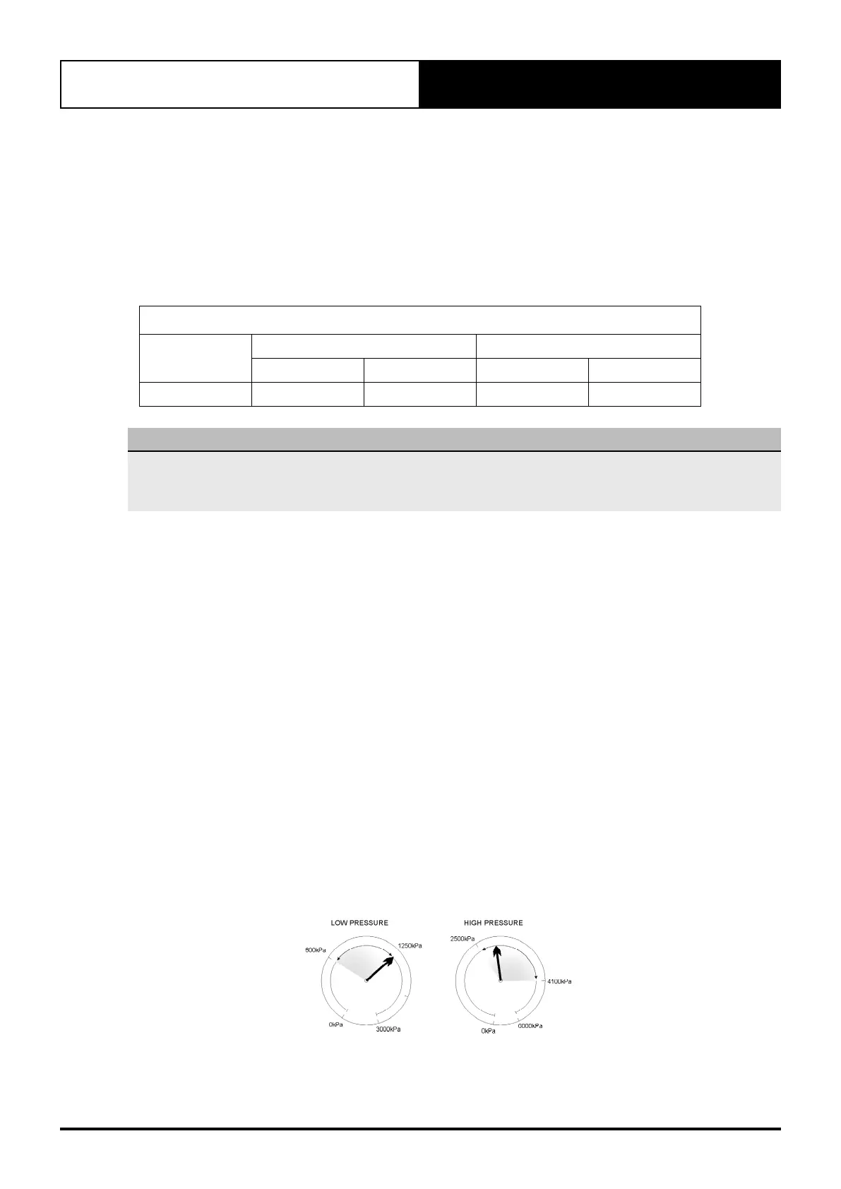
Gauge Reading
When running at 100%, ESP system will operate the same as a standard (classic) ActronAir system, with gauge
pressure operating as normal.
When compressor is modulating, gauges reading will rise and fall.
High pressure gauge will rise when the compressor is loaded and fall when the compressor is unloaded.
Low pressure gauge will fall when the compressor is loaded and rise when the compressor is unloaded.
Copyright © 2007 ActronAir. All rights reserved. 0500-050
Ver. 02
For further info see www.actronair.com.au
R-410A ESP QUICK COMMISSIONING GUIDE
Gauges During Modulation
Typical Rise and Fall of Gauges during Modulation
Auto Heat Cool Mode Operation Time Chart
Showing Cooling to Heating change over.
SET TEMP
TIME
(SET TEMP - 4)
(SET TEMP + 4)
ROOM TEMP
( C)
COMPRESSOR
AMBIENT
TEMP.
WARMER COOLER
Cooling
(MODULATING 10 - 100%)
Cooling
(100%)
OFF
Heating
(MODULATING)
(SET TEMP - 1)