Cold water
Hot water
1 2 3
4
5
6
7
8
9
11
10
12
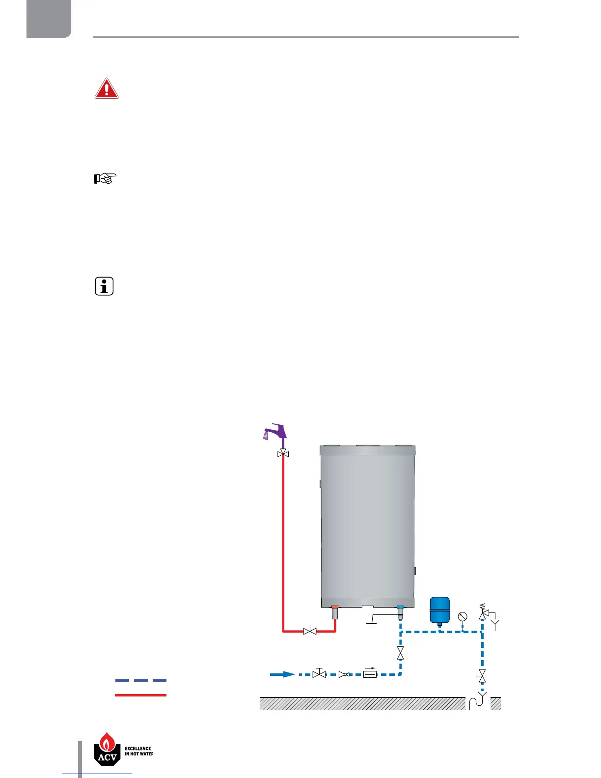
CONNECTION TO THE DHW CIRCUIT (Typ. vertical installation on a wall)
Key
1. Filling valve
2. Pressure reducing valve (set at 4.5 bar)
3. Check valve
4. Stop valve
5. DHW expansion vessel
6. Pressure gauge
7. Safety valve (set at 7 bar)
8. Drain valve
9. Grounding
10. Stop valve
11. Thermostatic mixing valve
12. Hot water outlet
CONNECTION
Essential instructions forthe safety of persons and the environment
• Refer to the safety instructions for the installation. Failure to comply with these
instructions can result in damages to the system, severe injuries or death.
• Hot water can burn! ACV recommends using a pre- set thermostatic mixing valve
in order to provide hot water at a maximum of 60°C.
Essential instructions forthecorrect operation ofthesystem
• The filling circuit of the DHW tank must be equipped with a safety group,
comprised at least of a stop valve, a check valve, a safety valve set at 7 bar, and
possibly, an expansion vessel of the appropriate size. Make sure that the circuit
between the tank and the safety valve is always open.
• The third DHW tank connection, if any, can be used for the auxiliary DHW loop. If the
connection is not used, replace the protective plug by a brass plug of the appropriate
size.
General remarks
• In certain countries the domestic kits must be approved.
• The circuit illustrations are basic principle diagrams only.