953.160UK User Manual
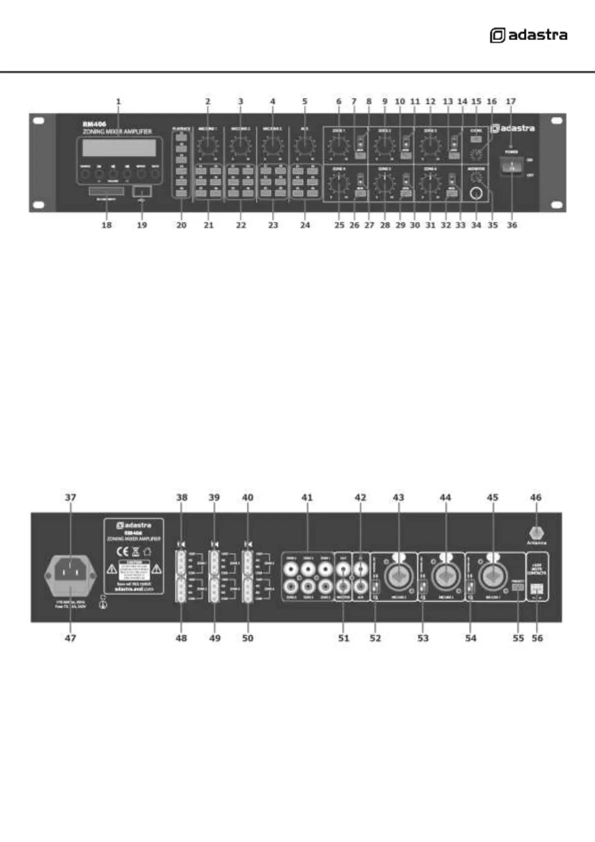
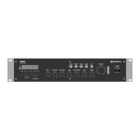
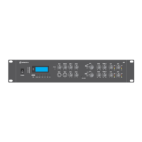
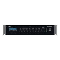
Front panel
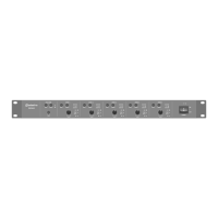
Rear panel
Media playback zone assign buttons
Mic/Line 1 zone assign buttons
Mic/Line 2 zone assign buttons
Auxiliary line input level control
Mic/Line 3 zone assign buttons
Zone 1 output level control
Auxiliary line input zone assign buttons
Zone 1 monitor send button
Zone 4 output level control
Zone 1 output LED indicators
Zone 4 monitor send button
Zone 2 output level control
Zone 4 output LED indicators
Zone 2 monitor send button
Zone 5 output level control
Zone 2 output LED indicators
Zone 5 monitor send button
Zone 3 output level control
Zone 5 output LED indicators
Zone 3 monitor send button
Zone 6 output level control
Zone 3 output LED indicators
Zone 6 monitor send button
Zone 6 output LED indicators
Chime output level control
Monitor headphones output
Monitor output level control
Mains power inlet (IEC) and fuse holder
Zone 1 speaker output terminals
Zone 2 speaker output terminals
Zone 3 speaker output terminals
Zone 4 speaker output terminals
Zone 5 speaker output terminals
Zone 6 speaker output terminals
Zones 1-6 line level outputs (RCA)
Monitor line level output (2 x RCA)
Channel 4 Auxiliary input (2 x RCA)
Channel 3 DIP switches (mic/line + phantom)
Channel 3 Mic/Line input (XLR/jack)
Channel 2 DIP switches (mic/line + phantom)
Channel 2 Mic/Line input (XLR/jack)
Channel 1 DIP switches (mic/line + phantom)
Channel 1 Mic/Line input (XLR/jack)
Channel 1 priority switch
24V emergency mute contacts