AGLAS Master Control Device
AGLAS Master Introduction
© ADB SAFEGATE All Rights Reserved
10
96A0480 Rev. B
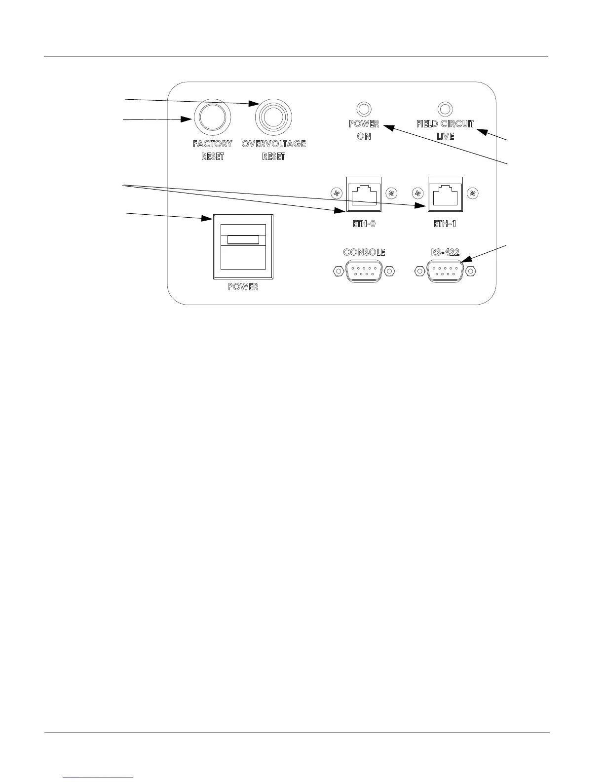
Figure 4: Front panel of the Control Unit of the AGLAS Master
The Control Unit’s individual operation and display elements have the following functions:
1. Power On LED red
— Constant current regulator is switched on.
2. Field Circuit Live LED amber
— System is running
3. Service 9-pin RS-422 connector
— RS422 system service connector
4. eth 0 and eth 1, Eth RJ-45 interface
— 100Mbit TCP/IP network interface
— For communication with AGLAS PC via a hub or switch. The user can determine the IP address that must be assigned to
this connection (software function).
— The address (MAC ID) of the interfaces are found on the ABOUT screen of the AGLAS Master.
5. Main Power connections
— Main power switch
6. Factory Reset
— This button resets AGLAS Master to the delivery condition (FLASH pages including the current configuration, logs and IP
addresses are deleted).
— Hold the reset button down from power on until the master reboots.
7. Over-voltage Protection Reset
— Illuminates when tripped
— Push to reset