2.3 Power Supply Setting & Connections
2.3.1 Power Supply Setting
The instrument operates from single phase, 110, 220 or 240 volts nominal AC, at 50 or 60 Hz.
The supply frequency is not critical, but the voltage must be set on the instrument to suit the
local power supply.
The voltage setting and connections are on the rear panel.
On delivery, the instrument is usually set for 240 volts operation. In this case, the number '240’
can be seen in the window of the voltage selector, just below the inlet socket.
If 220VAC or 110VAC operation is required, the voltage setting must be changed via the
combined voltage selector and fuse holder.
The selector is removed by pushing down the dip and pulling the fuse out. Pull the fuse holder
out and rotate it so that the voltage required shows in the selector window. If necessary,
change the fuse according to the table below.
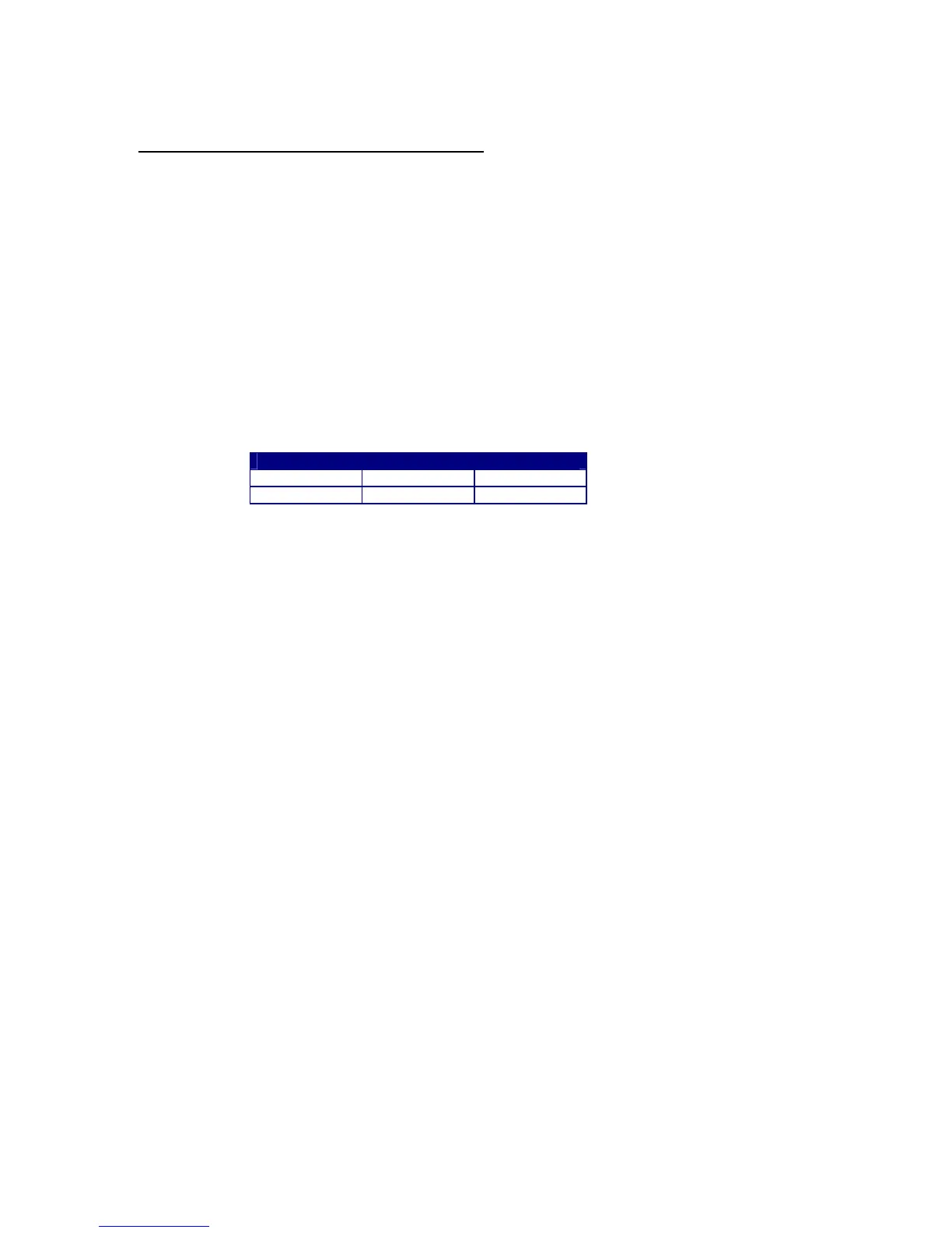
Supply Fuse Ratings
110V 220V 240V
2A T 1A T 1A T
Spare fuses are provided which are 20 X 5 mm ceramic HRC ‘T’ (Time Delay) types.
Maximum Power consumption is 120VA.
2.3.2 Power Supply Connections
The power cable supplied must be connected to a suitable plug or distribution board
as follows:
BROWN - Line or High Voltage
BLUE
- Neutral or Low Voltage
GREEN/YELLOW - Earth or Ground
For safety reasons the Earth connection MUST provide a low resistance to Ground.
Further protection is provided by making a direct Earth-Bonded connection to the chassis of the
instrument, via a 4mm screw. This bonding is just below the voltage selector.
The instrument is provided with an ON/OFF switch under the power socket.
WARNING
• If the front, top or bottom sections of the enclosure are removed, BEWARE of
HIGH VOLTAGES near the power connector, switch and internal supply.
• When REMOVING or REPLACING the enclosure sections ALWAYS disconnect the
mains supply FIRST.
 Loading...