3.5 Analogue (Chart) Outputs
An analogue output is provided for each gas measured (up to 4 channels). The outputs are
available from a circular DIN type connector on the rear panel. Outputs are set for 0..10V at
the factory, though they can be changed for voltage output of 0..1V, 0..5V, 0..10V or current
output 4..20mA. See section 2.5.1.
The outputs are arranged so that the gas shown on the top line of the screen is presented on
analogue output 1. The gas shown on the second line of the screen (if any) is presented on
output 2 and so on.
Analogue output scaling is fixed and corresponds to the full scale measurement range of the
associated gas. Analogue outputs do not indicate negative or over-range conditions.
3.6 Alarm (Trip) Outputs
The MGA analyser features up to five electrically isolated alarm contact outputs. The alarms
can be set up individually from the front panel to indicate gas readings above or below a set
value, inside or outside a set range, or to indicate sample error.
The number of trip contacts fitted may vary depending on the specification ordered.
For connection information, see section 2.6.
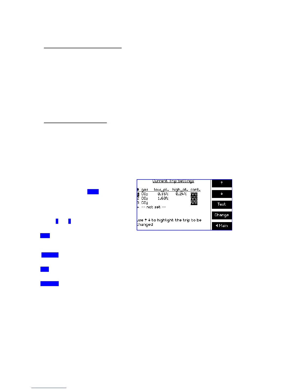
3.6.1 Setting Alarm Outputs
The alarm outputs are not set at the factory.
To set or check the alarm settings from the
main screen, press the ‘Trips’ function key.
The screen will list the settings for each trip
fitted. If no alarms are fitted, a warning
message will appear before returning you to
the main screen.
Use the ↑ and ↓ keys to highlight a trip then
press:
‘Test’ To temporarily set a trip to the alarm
state – allowing connected equipment to be
tested.
‘Change’. To modify settings for the selected trip. The screen will display the selected trip,
and the function keys now offer items to change. From this screen use:
‘Gas’ to select the gas for which this trip is active, or alternatively select ‘not set’ (trip not
used) or ‘flow error’ (active if sample flow out of range).
‘Lo point’ to set a gas value below which the trip is active. If there is no reading shown under
this column on the display, or if the ‘Off’ key is used when setting the low point, this trip will not
respond to low readings.
Figure 8 - Trip settings screen
 Loading...