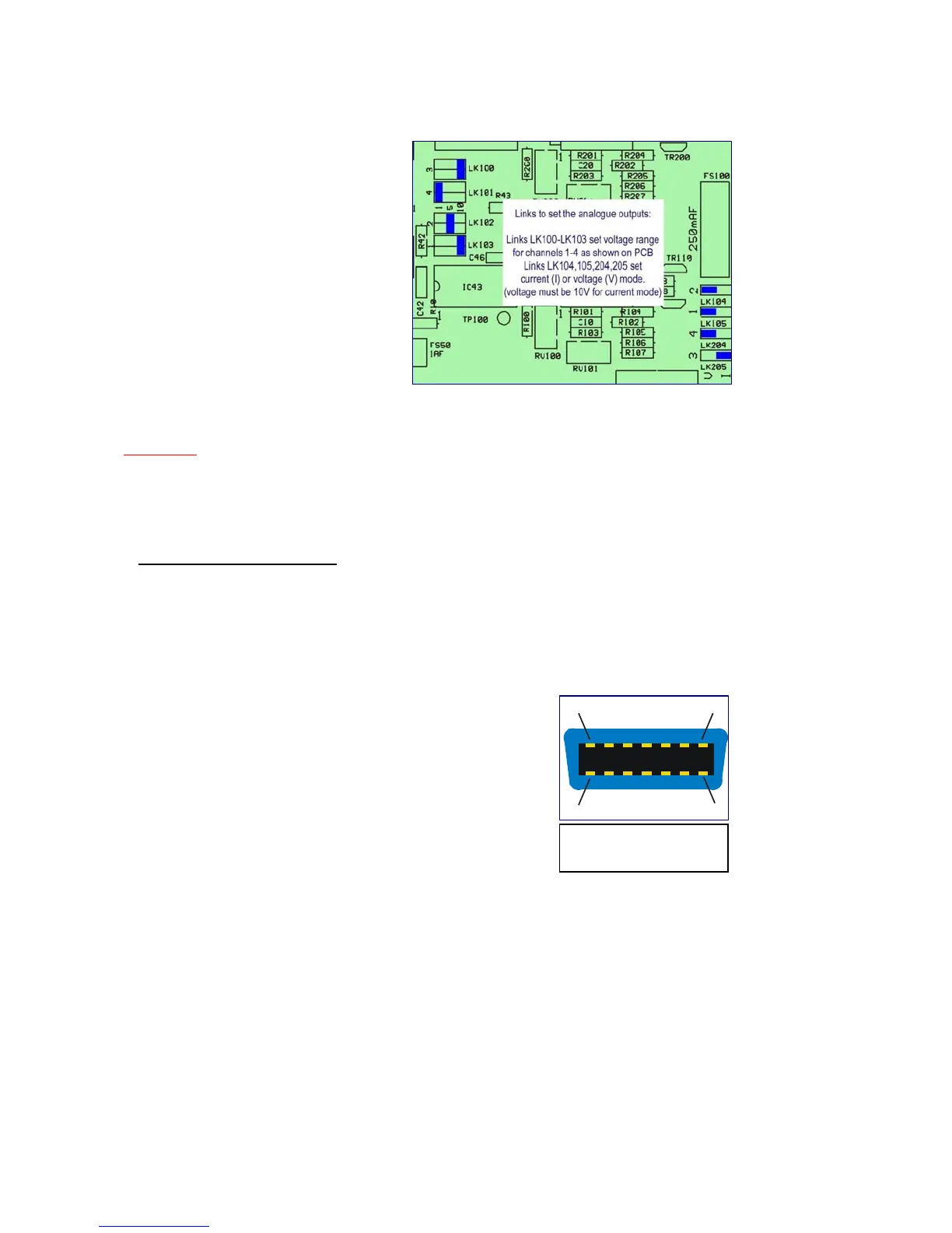
5. In the drawing, the jumper settings
shown illustrate the different settings as
follows:
Output 1 – 10V
Output 2 – 5V
Output 3 – 4.. 20mA
Output 4 – 1V
6. Set the links as required, by pulling
them off the pins with tweezers or a
small pair of pliers, and then very
carefully re-seat them in the new
positions. The links should slide on
easily if they are aligned correctly.
7. Re-fit the top panel completely before
making connections and applying
power.
WARNING
Applying voltages to analogue outputs set to voltage mode will cause damage!
Check link settings before making connections
2.6 Alarm (Trip) Outputs
The alarm outputs are isolated relay contacts which can be set to operate at certain gas levels,
or on sample flow error. Up to five contacts may be available depending on the specification of
the instrument. The number actually available is shown on the trip set-up screen (see section
3.6.1).
Alarm contact outputs are available via a 14 way Amphenol connector on the rear panel. A
suitable connector is provided in the kit with each instrument, and further supplies are available
from ADC (Spares & Service) Ltd. or their authorised local agent.
The connector pin functions are printed on the rear panel adjacent
to the connector, and the pin numbering scheme is shown in Fig 4.
See section 7.3 for specifications.
A nominal 24 Volt (±20%) DC supply is available at the alarm
connector which can be used to power larger relays, sirens,
indicator lamps etc. This power source is internally fused at 1A
and the maximum continuous load is 500mA. The +24V DC
supply is referenced to chassis ground.
Figure 3 - Position of the Voltage/Current selection
links on the PCB
(rear panel view)
7
14
Figure 4 - Alarm
connector pin numbers
 Loading...