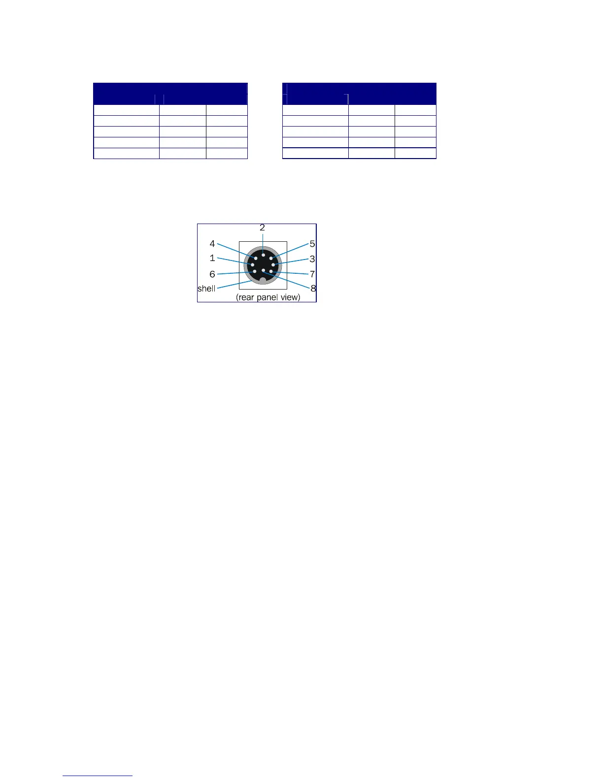
mA
+ -
Channel 1 3 8
Channel 2 7 5
Channel 3 2 4
Channel 4 6 1
NOTES:
1. V is used to indicate pin functions when output is set to voltage mode
2. I is used to indicate pin functions when output is set to 4..20mA mode
3. Screened cable should be used for analogue output connections (screen to connector shell).
Each output can be set to one of:
• 0 – 1V ]
• 0 – 5V ]- voltage modes
• 0 – 10V ]
• 4 – 20mA - current mode
Independently, using jumper links inside the case as shown in the section below.
2.5.1 Setting the analogue outputs
The procedure is as follows:
1. Disconnect the mains supply from the analyser, together with all the signal cables.
2. Isolate gas supplies, then remove the gas connections if necessary, taking all necessary
precautions.
3. Remove the top cover from the instrument by undoing the six screws on the top face, and
two screws on the back edge of the cover plate. Lift the cover clear.
4. Locate the RS232C connector on the rear panel, then look inside to locate the connector on
the circuit board (PC 392). The jumper links are all near to the RS232 connector, as shown
on the drawing (Fig. 3).
Voltage
+ -
Channel 1 3 8
Channel 2 7 5
Channel 3 2 4
Channel 4 6 1
Figure 2 – Analogue Output
pin numbers
 Loading...