contrast adjustment. If it is not possible to get good contrast within the range of the bar, press
the ‘Default’ key, then, using a 2mm flat-bladed screwdriver, adjust the ‘LCD’ control through
the labelled hole in the back panel for best display. Note that the rear panel control has a wide
range and the display will not be visible for extreme settings.
3.4.2 Function Keys
The instrument is operated using the five function keys to the right of the display screen. The
keys are labelled on the display, allowing the functions of the keys to change dynamically as
options are selected.
3.4.3 Menus
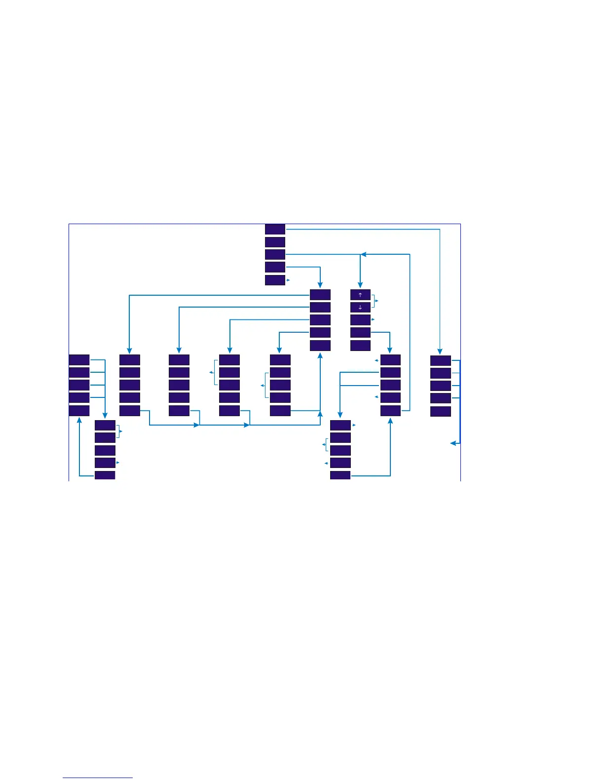
Fig. 7 shows the menu ‘tree’, starting from the main screen showing the sample gas readings.
Sub-menus provide routes to more detailed functions, until the operator is required to 'DO' an
action. At this point, the display will present instructions, or more information, appropriate to
the action required.
For example, pressing the function key 'Zero adj' on the main menu, presents a Sub-menu with
the function keys on the right hand side of the display and instructions on the bottom of the
screen.
Zero Adj.
(gas 1)
Display
Gas
Darker
OffBaud
Span Adj.
(gas 2)
Ser.Port
Lo Point
Lighter
+Handshk. Z to mid
Set Up
(gas 4)
Diags
Contacts
Change
-
Tes ts
Stp.Pump
< Main
< Main
Done
< Main
Done
Done
< BackDone < Back
Trips
(gas 3)
(gas 1)
(gas 2)
(gas 4)
< Main
(gas 3)
Gas +
Gas -
Set Span
< Back
Auto Z.
Hi Point
Tes t
+
++
Off
Default
-Outputs.
Start/Stop
Sample Pump
‘Set’ the trip
Cycle through the
possible gasses
& flow error
diagnostic
functions
zero
time
select
trip
Main Menu
select n/o or n/c
increment trip point
adjust span
gas value
disable trip level
adjust span
for selected gas
set zero for gas
(if fitted)
decrement trip point
Figure 7 - the complete 'menu tree'.
 Loading...