Page 4 of 84
Table of Figures:
Figures:
Figure 1: Label Placement Drawing .................................. 6
Figure 2: Sample Unit Data Plate .......................................7
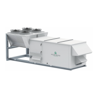
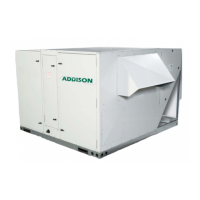
Figure 3: Large Unit Lifting ..................................................18
Figure 4: Medium Unit Lifting .............................................19
Figure 5: Small Unit Lifting .................................................20
Figure 6: Roof Curb Installation ......................................... 21
Figure 7: Circuit Diagram for Standard Compressor .
with Hot Gas Bypass and No Hot Gas Reheat .........24
Figure 8: Circuit Diagram for Standard Compressor
with Hot Gas Bypass and Modulating Hot Gas
Reheat ...........................................................................................25
Figure 9: Circuit Diagram for Digital Compressor
with Modulating Hot Gas Reheat ....................................26
Figure 10: Circuit Diagram for Standard Compressor
with Hot Gas Bypass and Modulating Hot Gas
Reheat and Subcooling ........................................................ 27
Figure 11: Circuit Diagram for Digital Compressor .....
with Modulating Hot Gas Reheat, and Subcooling 28
Figure 12: Example Energy Recovery Wheel .............29
Figure 13: Example Gas Heater Wiring Diagram -
5:1 Modulation ...........................................................................35
Figure 14: Example Gas Heater Wiring Diagram -
10:1 Modulation .........................................................................36
Figure 15: Example Gas Heater Wiring Diagram -
Dual Furnace .............................................................................. 37
Figure 16: Typical Electric Heater Wiring Diagram .40
Figure 17: Typical Electrical Wiring Diagram .............42
Figure 18: Phase Monitor Data .......................................... 49
Figure 19: Equipment Touch Display ............................... 51
Figure 20: P-Trap Configuration .......................................55
Tables:
Table 1: Recommended Torque Settings .......................15
Table 2: Manifold Size and Minimum Pressure ........30
Table 3: Standard Electric Heaters .................................39
Table 4: Low Voltage Wiring Lengths ............................. 41
Table 5: Condensate Connection Sizes ........................54
Table 6: Hot Water Heating Coil Flow Rate ................56
Table 7: Superheat and Subcooling - 100% OA........56
Table 8: Superheat and Subcooling - Recirc .............56
Table 9: Superheat and Subcooling - Heat Pump ... 56
Table 10: Refrigerant Temperature-Pressure ..............57
Table 11: Maintenance Guidelines ....................................67
Table 12: Air Filters ..................................................................69
Table 13.1: Supply Fan .............................................................71
Table 13.2: Compressor ......................................................... 72
Table 13.3: Refrigeration Circuit ........................................ 74
Table 13.4: Variable Speed Heat Pressure Control ..76
Table 13.5: Energy Conservation Wheel .......................78
Table 13.6: Gas Furnace ........................................................ 79
Table 13.7: Electric Heater ....................................................80
PR Series Installation, Operation, and Maintenance Manual