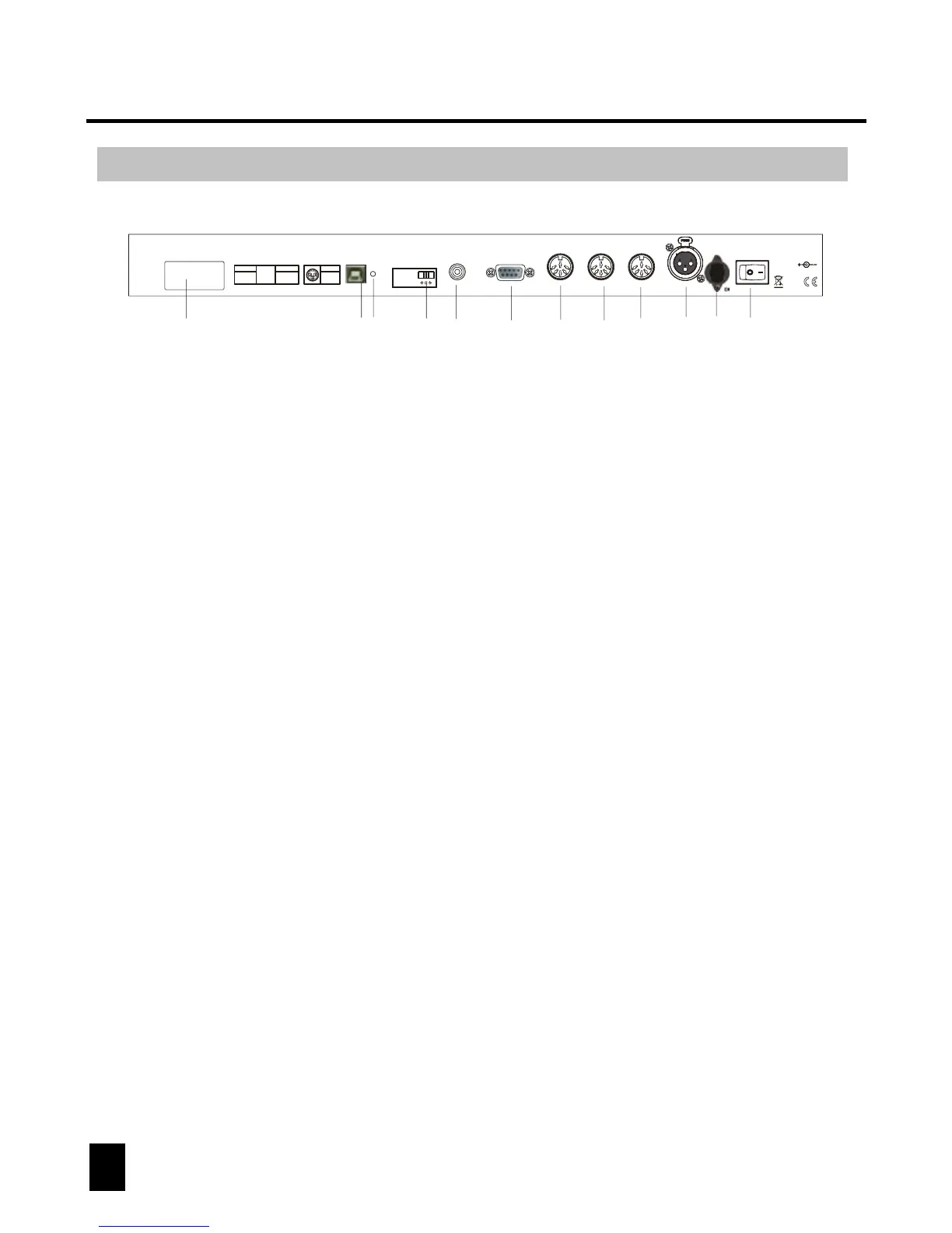
Rear Panel Overview
4. MIDI IN:
to receive MIDI information from a midi sequencer or compatible device.
6. 3 Pin Female XLR:
DMX output. Connect to first device in line.
2. Audio input:
to connect line level input for audio trigger (0.1V-1Vp-p).
7. DC INPUT:
connects the included power supply to this input. (DC 9V~15V, 500mA Min).
3. DB-9 connector:
to connect optional external chase step controller.
1. Label:
lists model, serial number and production date.
8. Power switch:
used to switch the units power on and off.
5. Fog machine connector:
to connect a compatible fog machine.
9. USB Interface:
outputs the MIDI signal via USB interface when connected to MIDI controller.
10. LED Lamp:
indicates the working state of USB interface.
11. Switch:
switches the function of DMX controller or MIDI controller. The change will work
after re-startup.
12. MIDI Out Socket:
output the MIDI signal when connected to the MIDI controller.
6
DMX OPERATOR 384
5
3
2
4
1
Midi In
Midi Out
1=NC; 2=GND
3=NC; 4=V+
5=Signal
1=NC; 2=NC
3=NC; 4=V+
5=Signal
Made in PRC
DC input:
9V-12VDC, 500mA Min
1
2
5
4
36
8
7
910
11
12