(7) WIRING
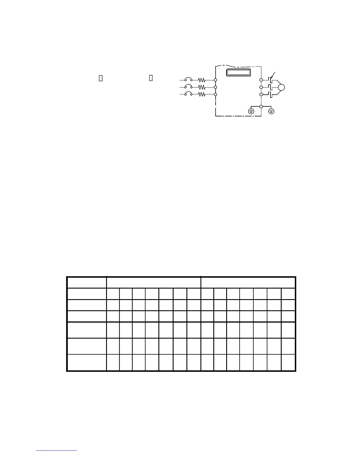
7-1 Wiring of main circuit
AP2G3 3 and AP4G3 3
power source terminal
connect R/L1, S/L2, T/L3.
7-2 Wiring equipments
Select the wiring equipment and wiring size, refer to the table
below.
1. On the input power side, a molded case circuit breaker (MCCB)
to protect inverter primary wiring should be installed.
2. A leakage current breaker threshold of 200mA and above, or of
inverter use is recommended.
3. Use of input side magnetic contactor. An input MC can be used to
prevent an automatic restart after recovery from an external power
loss during remote control operation. However, do not use the MC
frequently for start/stop operation, or will lead to a reduced reliabil-
ity.
4. In general, magnetic contactors on the output of the inverter,
Should not be used for motor control. Starting a motor with the
inverter running will cause large surge currents and the inverter
overcurrent protector to trigger.
R/L1
S/L2
U
V
W
APxG3-Series
IM
E
POWER
T/L3
THRY
SOURCE
Model AP2G3 AP4G3
Model No 337 355 375 3110 3150 3185 3220 337 355 375 3110 3150 3185 3220
Capacity (KVA) 6.5 9.2 12.6 17.6 23.3 29 34 6.5 9.2 12.6 17.6 23.6 29 34
Current (A) 17 24 33 46 61 76 90 8.5 12 16.5 23 31 38 45
Circuit Breaker
(MCCB) (A)
20 30 50 75 100 125 150 15 20 30 50 50 75 75
Electro-Magnetic
Contactor (A)
18 35 50 65 80 93 93 12 18 18 35 48 50 50
Thermal relay
RC value (A)
15 20 28 40 55 67 80 6.8 9 15 20 28 40 40