(a) (b) (c)
15
7-5 Wiring and cautionary points
A. Main circuit
1. Don’t connect the cables of the power supply side (R/L1,S/L2,T/
L3) to the U, V and W output terminals for the motor.
2. Don
’t connect any electromagnetic contactor between the
inverter and motor. If it is inevitable, turn on the contactor when
both the inverter and motor are both at stand still.
3. Don
’t put the advance phase capacitor between the inverter and
motor.
4. Put MCCB in the input power supply.
B. Control signal circuit
1. Separate the power cables of main circuit etc. from the control
cables of the sequence and analog signals by passing the cables
through the different ducts.
2. Use twisted pair shielded wire for control signal and connect the
shield to earth terminal at on end, COMMON terminal of
control board. Leave the other end of shielding open.
3. Avoid common Ground leads between high and low level
voltage equipment.
C. Grounding
1. Be sure ground both the inverter and motor.
2. Keep grounded leads as short as possible.
3. Shield cables used to protect low-level signal leads should
grounded at one end point.
4. Provide class 3 grounding (0.1
Ω or less) for a terminal.
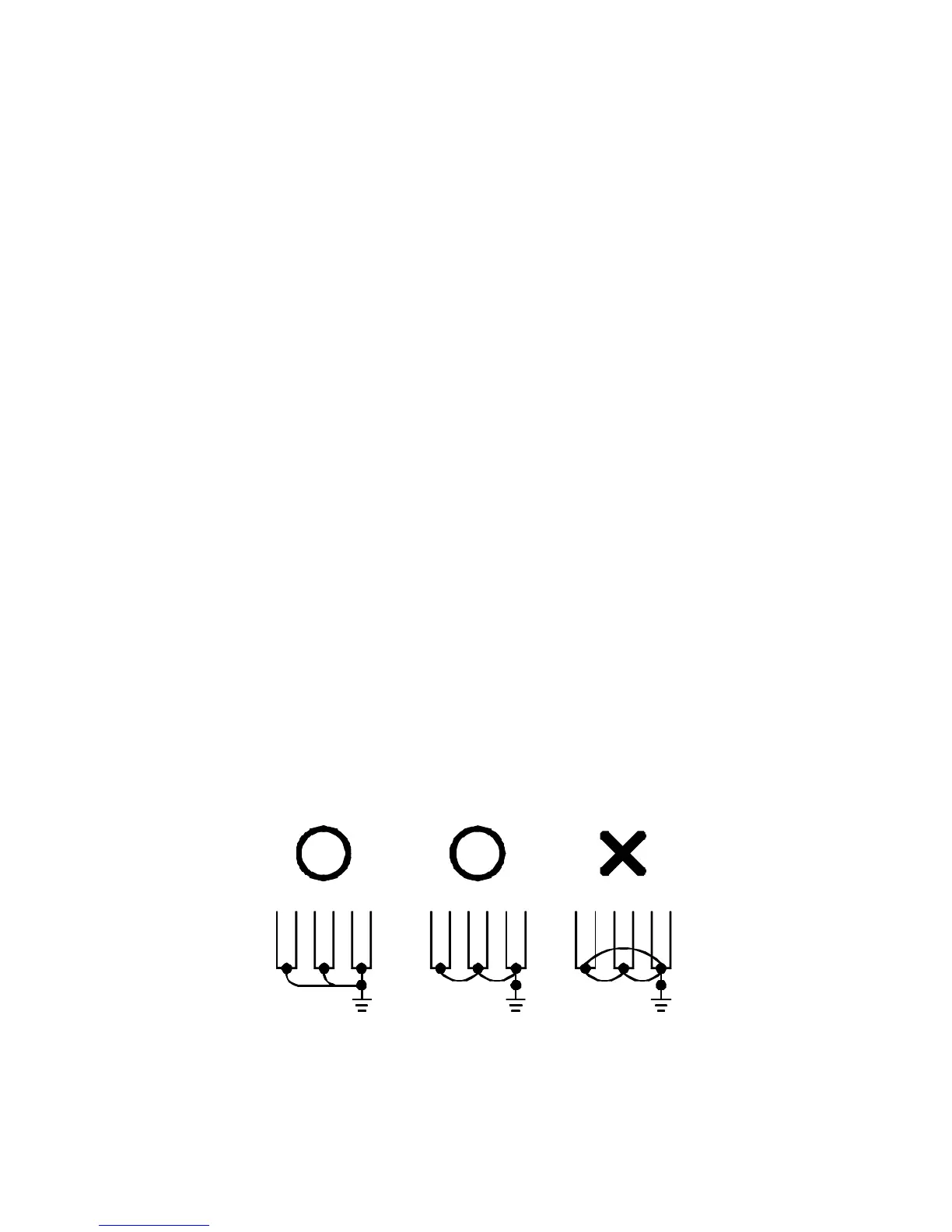
5. When grounding several inverters, make connections as shown
below, no loop is produced as shown in FIG
“a “ , FIG “b“ .