Physical Descriptions NetVanta 1230 Series Hardware Installation Guide
16 Copyright © 2009 ADTRAN, Inc. 61700594G1-34B
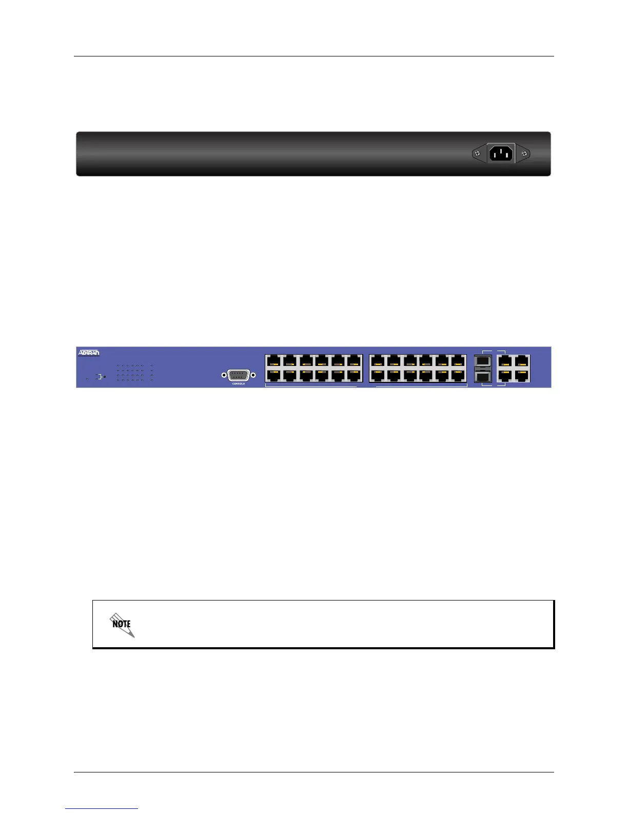
NetVanta 1234 Rear Panel Design
The NetVanta 1234 rear panel is shown below.
Figure 2. NetVanta 1234 Rear Panel Layout
NetVanta 1234 Rear Panel Interfaces
Power Connection
The rear panel has a power input to the AC universal power supply. Please refer to Supplying Power to
the Unit on page 25 for connection details.
NetVanta 1234 PoE Front Panel Design
The NetVanta 1234 PoE front panel is shown below. Table 1 on page 20 describes all of the LEDs, and
Appendix A on page 27 shows the connector pinouts.
Figure 3. NetVanta 1234 PoE Front Panel Layout
NetVanta 1234 PoE Front Panel Features
Status LED
The STAT LED indicates the unit’s status and the LEDs are located on the lower left corner of the unit.
Mode Selector Button
The mode selector button is used to select the type of activity displayed on the LEDs labeled
1 through 24. If LINK/ACT is selected, the LEDs display the link status/activity of the ports. If PoE is
selected, the LEDs display the status of PDs connected to the ports.
CONSOLE Interface
The CONSOLE interface is an EIA-232 serial port (DCE) that provides for local management and
configuration (via a DB-9 female connector).
10/100Base-T Ethernet Interfaces
The NetVanta 1234 PoE front panel contains 24 10/100Base-T Ethernet interfaces (RJ-45). These
interfaces are arranged in stacked pairs, with the numbers 1 through 24 screened directly above or
below the corresponding port. Status LEDs numbered 1 through 24 are located in the LED bank on the
left side of the unit.
Connection directly to an external modem requires a cross-over cable.
100-240 VAC
50-60 Hz
0.5A MAX
G2
G3
G4
NetVanta 1234
7
1
2
3
4
5
6
7
8
9
10
11
12
13
14
15
16
17
18
19
20
21
22
23
24
G1
G2
G3
G4
Power over Ethernet
1 3 5 9 11 13 15
2
4
6
8
10 12
14
16
17 19 21 23
18
20
22
24
STAT
G1
LINK/ACT
PoE

 Loading...