NetVanta 3100 Series Hardware Installation Guide Physical Descriptions
61700600L2-34C Copyright © 2015 ADTRAN, Inc. 19
NetVanta 3130 Rear Panel Design
The NetVanta 3130 rear panel is shown below. Appendix A on page 37 provides pinouts.
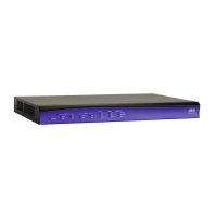
Figure 7. NetVanta 3130 (with DBU) Rear Panel Layout
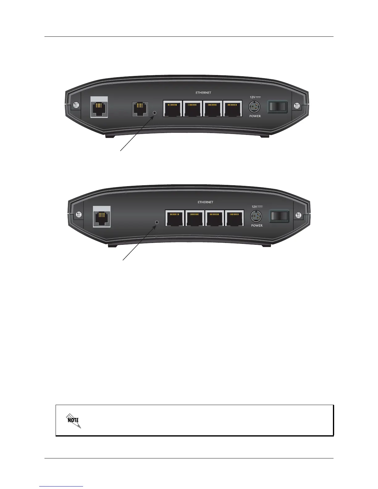
Figure 8. NetVanta 3130 (without DBU) Rear Panel Layout
NetVanta 3130 Rear Panel Interfaces
ADSL Interface
The NetVanta 3130 rear panel has an ADSL port to connect directly to ADSL, ADSL2, or ADSL2+
service. See Table A-5 on page 38 for the ADSL connector pinouts.
DBU Interface (1700610L2 only)
The NetVanta 3130 has a DBU port on the rear panel to provide analog, V.90 dial backup. See
Table A-4 on page 38 for the DBU connector pinouts.
Factory Default Switch
The NetVanta 3130 has a factory default switch (labeled in Figure 7) on the rear of the unit. If the
factory default switch is pressed during bootup, the unit will stay in bootstrap mode. Since the unit has
no serial port, Telnet has been built into the boot code. The default IP address is 10.10.10.1.
The default switch must be pressed WHILE the STAT light is flashing green. Do not
press the default switch BEFORE the STAT light is flashing green, as this will cause
boot to be missed.
1
DBU
23 4
ADSL
10
Default
Switch

 Loading...