2.2 Installing the Mx-4100 Enclosure
The panel can weigh in excess of 15kg when the batteries are installed. Use the appropriate
fixing hardware to secure the panel to the wall. Observe recommended lifting practices to
guard against spinal injury.
2.2.1 Removing and Replacing the Enclosure Cover of the Mx-4100
The enclosure cover is fixed in place with two tamper resistant hexagon key screws. These require the use of a
2.5mm Allen Key. The enclosure cover must be connected to earth. When replacing the cover, always ensure
that the earth lead spade terminal is securely seated onto the blade terminal in the back box.
2.2.2 Removing the Chassis
It is recommended that the chassis be removed before fitting the panel to the wall. To remove the chassis:
Disconnect the earth cable connecting the chassis to the spade terminal on the rear enclosure.
Remove the two screws holding the chassis to the back box. Keep these items in a safe place for later re-use.
Unplug the 3-way connector feeding the power supply to the Base Card. Carefully remove the chassis from the
rear enclosure and place in a safe place to prevent accidental damage.
Do not lift the chassis by holding onto any of the printed circuit cards. Hold the chassis by the
metal plate only.
2.2.3 Mounting the Enclosure
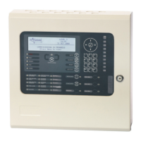
Firstly, remove the required knockouts for the installation wiring. There are sufficient knockouts on the top of the
enclosure for all installation wiring. In addition, there are knockouts at the top of the back wall, if required, for
rear entry cabling.
The enclosure is provided with four fixing points.
The diagram opposite shows the positions of the
four holes. Use all four positions to ensure the
panel is held securely to the wall.
Drill the required holes in the supporting wall using
a drill bit diameter 7.0 mm and plug with a suitable
40mm long expansion plug. Affix the panel to the
wall with M5 screws (length 40mm) or No.10
screws (length 1½”).
Ensure that there is sufficient space to allow the
cover to be removed / replaced when the panel is
mounted.
Finally, use a brush to remove any dust or swarf
from inside the enclosure.
Cable Tie
Anchor Points x6
Enclosure Size and Fixing Point Dimensions
2.2.4 Remounting the Chassis
Carefully replace the chassis and fix into place using the two screws.
Reconnect the chassis earth cable to the spade terminal in the rear of the enclosure and then reconnect the
supply lead from the transformer to the Base Card.