The Advanced
®
Model 3250/4250 Service Manual
48
1. Turn on the instrument. If there is a
Supervisor/Operator keyswitch, turn it to
the Supervisor position (if required).
Place an empty sample tube in the sample
well.
2. Press TEST. Press < or > to select
“Head Up/ Down Test”, and then press
START.
3. Place an empty sample tube into the
freezing chamber.
4. At “[START] Test [STOP]”, press
START.
The head should move continually up and
down.
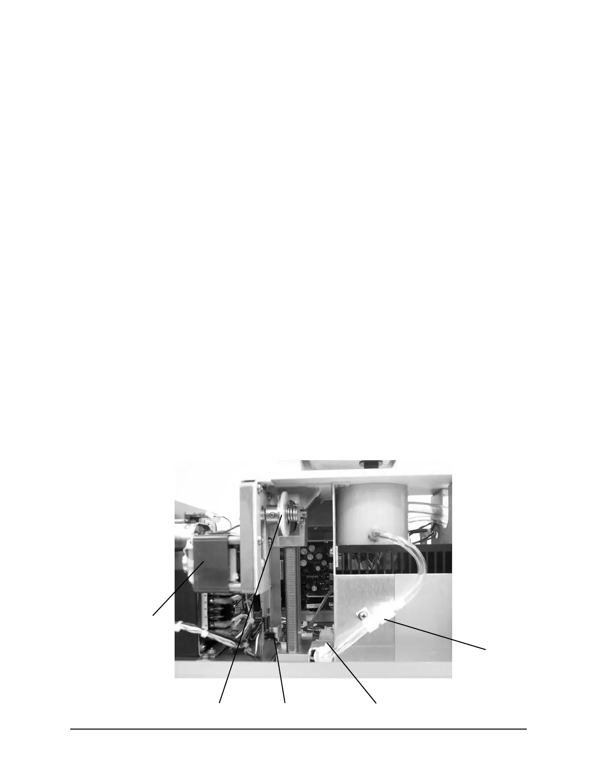
Use this test to ensure the following compo-
nents are working properly:
• The motor (A) is running.
• The gears (B) are turning properly.
• The sensors (C) are detecting the head-up
and head-down conditions.
• The sample well fluid passage (D) is not
obstructed by debris, and the pump is mov-
ing the heat transfer fluid into the freezing
chamber.
Note: If the sample well fluid passage is
obstructed, disassemble and clean the
sample well following the instructions
found earlier in this section. Also,
examine the one-way check valve (E)
to make sure it is not stuck open or
closed.
Note: Your instrument is equipped with a
series of diagnostic LEDs on the main
application board PCB605 to allow
visual identification of drive signals
and sensor activation.
• The yellow LEDs marked “Drive
Up” and “Drive Dn” indicate that
the control electronics have issued a
command to the head motor relays.
• The red LEDs marked “Head Up”
and “Head Dn” indicate that the
corresponding optical sensor has
been tripped.
A
B
C
D
Head Up/Down Test
E