The Advanced
®
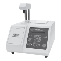
Model 3250/4250 Service Manual
27
Serial (RS-232) Port Interface: An RS-232
line driver/receiver provides the microproces-
sor with a serial port interface that supports
both hardware and software handshaking.
The DB-9 RS-232 port conforms to the DTE
RS-232C standard and has the following pin
assignments:
Signal Pin Direction
Carrier Detect 1 to 3250
Receive Data 2 to 3250
Transmit Data 3 from 3250
Data Terminal Ready 4 from 3250
Signal Ground 5 common
Data Set Ready 6 to 3250
Request to Send 7 from 3250
Clear to Send 8 to 3250
Note that your instrument is only designed to
support unidirectional communication with an
external device. At this time, there is no pro-
tocol for bidirectional communication.
For a sample RS-232 Port Setup, please see
the RS-232 Supplemental Information in the
Appendix at the end of this user’s guide.
Note: This instrument requires the use of a
null modem RS-232C cable. There are
several variations on null modem
cables. Advanced Instruments recom-
mends that you purchase a RS-232C
cable direct from our factory.
Supervisor/Operator Keyswitch Interface:
A PLD is used to interface the supervisor/
operator keyswitch to the microprocessor. In
Operator position, the user cannot change
setup or calibration settings.
Other Circuit Components
Drive Circuitry, Serial Suffix A - C: Drive
circuitry is provided to turn on and off the
four high current loads such as the stir wire,
the head motor, the thermoelectric cooler, and
the fan.
The stir wire coil is controlled by the rear
panel-mounted darlington transistor
(PCB522). The drive circuit consists of a
programmable timer, D/A converter, and
interface op-amps. The timer provides a
square wave of approximately 71Hz, while
the D/A converter controls the output ampli-
tude to the darlington transistor.
The head motor is controlled by two relays
located at the rear of the chassis that interface
the 120 VAC motor to the DC logic. One
relay raises the head, while the other relay
lowers the head. The relays get their com-
mands from the application board via two
FETs and the application logic. LEDs are
provided on the application board for moni-
toring the drive signals. LEDs are also pro-
vided to monitor the signals from the head
sensor board, described below.
The thermoelectric cooler is controlled by the
FET driver transistor mounted on the rear
panel (PCB520). The FET is, in turn, con-
trolled by the microprocessor through the
PLD application logic. The processor varies
the duty cycle square wave in response to
software commands and block probe resist-
ance.
Drive Circuitry, Serial Suffix D and
Higher: Drive circuitry is provided to turn
on and off four system loads such as the stir
wire, the head motor, the thermoelectric cool-
er, and the fan.
The stir wire coil drive circuit consists of a
programmable timer, D/A converter, and
interface op-amps on the application board
(PCB605). The timer provides a square wave
of approximately 71 Hz, while the D/A con-
verter controls the output amplitude to the
darlington transistor mounted on the driver
board (PCB523).
The thermoelectric cooler is controlled by the
microprocessor through the PLD application
logic. The processor varies the duty cycle
square wave in response to software com-