1. Turn off the power and unplug the instru-
ment. Remove the instrument cover and
the head cover. Place an empty sample
tube in the sample well.
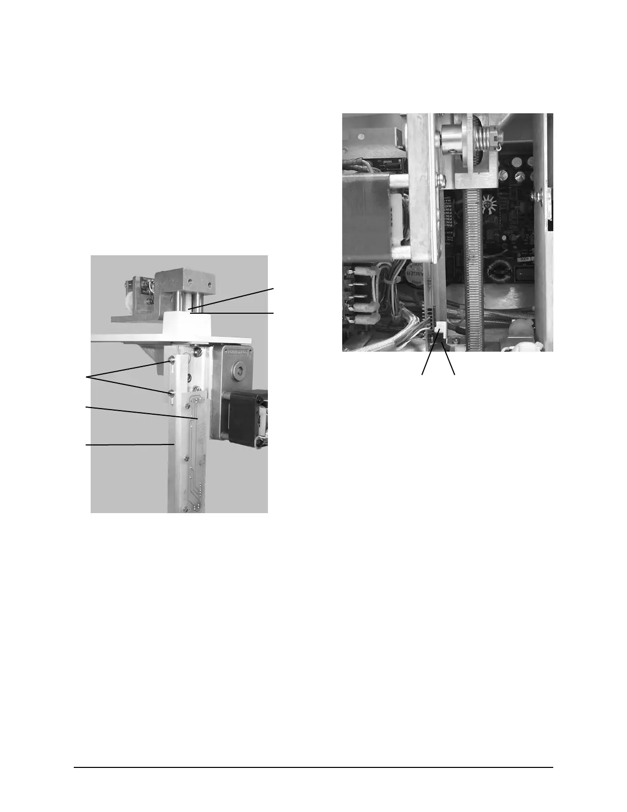
2. Manually push the head all the way down
until the head stop screw (A) meets the
base of the deck (B).
3. The head position sensors are located on
the head sensor board. To adjust the head
sensor position, use an Allen wrench and
loosen the two bracket screws (C), and
move the board (D) and bracket (E) either
up or down until the head sensor flag (F)
is in the middle of the head down sensor
(G).
Note: To facilitate access to the two bracket
screws (C), loosen and move the print-
er bracket assembly.
Note: Your instrument is equipped with a
series of diagnostic LEDs on the main
application board PCB605 to allow
visual identification of drive signals
and sensor activation.
• The yellow LEDs marked “Drive
Up” and “Drive Dn” indicate that
the control electronics have issued a
command to the head motor relays.
• The red LEDs marked “Head Up”
and “Head Dn” indicate that the
corresponding optical sensor has
been tripped.
B
A
C
D
E
F
G
Head Sensor Adjustment
47
The Advanced
®
Model 3250/4250 Service Manual