The Advanced
®
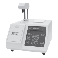
Model 3250/4250 Service Manual
54
Software for Advanced Instruments model
3250/4250 instrument is contained in factory-
installed integrated circuits called Flash
EPROMs, “Electrically Erasable Program-
mable Read-Only Memory”, and is some-
times referred to as “Firmware”.
This type of memory is furnished in two
PLCC (Plastic Lead Chip Carrier) devices on
the 325620/425620/325621/425621 processor
board at locations U3 and U4. U3 is the
lower 8 bits of the 16-bit processor address
bus, and U4 is the upper 8 bits.
Advanced Instruments products using this
“FLASH” technology can be field-updated
using a Windows PC and Advanced
Instruments serial cable. For the latest
instructions on performing the RS-232 port
firmware upgrade, consult the documentation
supplied with the upgrade package. For infor-
mation on available updates, consult
Advanced Instruments or your dealer.
Performing FLASH firmware update
Performing this update should not affect any
of your calibrations or system settings unless
the update has made changes to this area of
memory. For specific information, consult
the documentation included with the update.
Method without opening cover
Your instrument has a three-position
Operator/Supervisor keyswitch.
1. Turn off the instrument. Select the 45º
position between Operator and
Supervisor.
2. Attach the Advanced Instruments serial
cable between your PC and the instru-
ment.
3. Turn on the instrument. The display
should read “Flash BOOT Program”.
4. Perform the download, using the instruc-
tions provided with the update software.
After download is complete, the instru-
ment will reboot and report the new soft-
ware version.
5. Turn off the instrument and return the
Operator/Supervisor keyswitch to the
desired position.
Method with cover removed
Note: Since this procedure requires opening
the case, this update should be per-
formed only by an authorized techni-
cian.
1. Turn off the power and unplug the instru-
ment.
2. Remove the instrument cover (see section
2 for instructions on removing the instru-
ment cover).
3. Locate the
325620/425620/325621/425621 processor
board (smaller of two).
4. Locate SW1 dip switch on the processor
board if it is a 3-position switch. Locate
switch position 3 (lower switch) and
select the CLOSED, ON, or 1 position. If
it is a 4-position switch, locate switch
position 1 (upper switch) and select the
CLOSED, ON, or 1 position. Do not
change any other switch setting.
5. Attach the Advanced Instruments serial
cable between your PC and the instru-
ment.
6. Plug in and turn on the instrument. The
display should read “Flash BOOT
Program”.
7. Perform the download, using the instruc-
tions provided with the update software.
Instrument Software Updates