PROFINET NETWORK CONFIGURATION
SMD23E2 and SMD24E2 User’s Manual
ADVANCED MICRO CONTROLS INC.
126
7.5 Set the I/O Configuration
The SMD23E2 and SMD24E2 units require 10 Input Words (20 Input Bytes) and 10 Output Words (20 Out-
put Bytes). All required Input and Output Bytes are defined by the GSDML file and divided into suitable
modules. These settings are shown in the Table
T7.1.
Table T7.1 PROFINET I/O Configuration
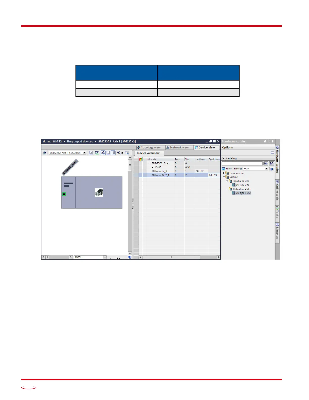
1) With the SMD23x2 icon selected on the PROFINET bus, click on the “Device view” tab. The view in the
Hardware Catalog will change. Expand the Module tree to show both the Input and Output modules.
2) To map the I/O bytes to the CPU, double click on the “20 bytes IN” and “20 bytes OUT” icons in the
Hardware Catalog. The system will automatically assign the next I and Q addresses to the data table.
Figure T7.4 I/O Byte Mapping
7.6 Verify and Download the New Configuration
1) Continue by adding any remaining devices to your PROFINET network.
2) Compile and download the project to the CPU.
Input / Output Bytes of an
SMD23E2 or SMD24E2
Input / Output Modules of an
SMD23E2 or SMD24E2
20 Input Bytes Input Module - Slot 1: 20 bytes
20 Output Bytes Output Module - Slot 2: 20 bytes