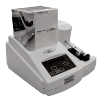
23
Software for the Advanced Instruments Model
3320 instrument is contained in factory-
installed integrated circuits called Flash
EPROMs, “Electrically Erasable
Programmable Read-Only Memory”, and is
sometimes referred to as “Firmware”.
This type of memory is furnished in two
PLCC (Plastic Lead Chip Carrier) devices on
the PCB120 processor board at locations U3
and U4. U3 is the lower 8 bits of the 16-bit
processor address bus, and U4 is the upper 8
bits.
Advanced Instruments products using this
“FLASH” technology can be field-updated
using a Windows PC and Advanced
Instruments serial cable. For the latest instruc-
tions on performing the RS-232 port firmware
upgrade, consult the documentation supplied
with the upgrade package. For information
on available updates, consult Advanced
Instruments or your distributor.
Performing FLASH firmware update
Performing this update should not affect any
of your calibrations or system settings, unless
the update has made changes to this area of
memory. For specific information, consult
the documentation included with the update.
1. Turn off the instrument.
2. Attach the Advanced Instruments serial
cable between your PC and the instru-
ment.
3. Locate the small hole in the back panel
sheetmetal between the barcode and serial
port connectors. Using an unfolded
paperclip or similar item, depress the
recessed switch behind the small hole
while performing the next step.
4. Turn on the instrument. After about four
seconds, the display should read “Flash
BOOT Program”. Remove the paperclip.
5. Perform the download, using the instruc-
tions provided with the update software.
After download is complete, the instru-
ment will reboot and report the new soft-
ware version.
If any problems occur, check the connections
and switch position settings, and then try the
download again. If after download the instru-
ment does not function correctly, consult the
rest of this service manual before contacting
Advanced Instruments for service.
Option Switch Settings
Processor board PCB120 is equipped with a
four-position dip switch. Each switch posi-
tion and combination of positions can be used
to configure different programming options,
such as the programming option listed above
for Flash update mode.
If your settings should accidentally get
changed, or your replacement processor board
is shipped from the factory with the incorrect
settings for your product, the following table
details the appropriate switch positions for
restoring your instrument to proper operation.
The Advanced
®
Osmometer Model 3320 Service Manual
Instrument Software Updates
SW1
1 2 3 4
Program ON OFF OFF OFF
210 OFF OFF OFF OFF
3320 OFF ON OFF OFF
NOTE:
ON = 1 = CLOSED
OFF = 0 = OPEN
Option Switch Setup Table