332P318 Rev1
(3325 Service Manual)
Page 2 of 3
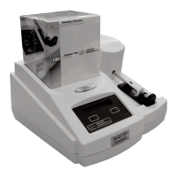
5. Return the instrument to its upright posi-
tion and carefully rotate the rear of the
cover up and away from the bottom cover
while keeping the front portion close to
the bottom cover (D).
6. Unplug the keypad cable (E) and the dis-
play cable (F) from the connectors on the
circuit board assembly, and remove the
instrument cover.
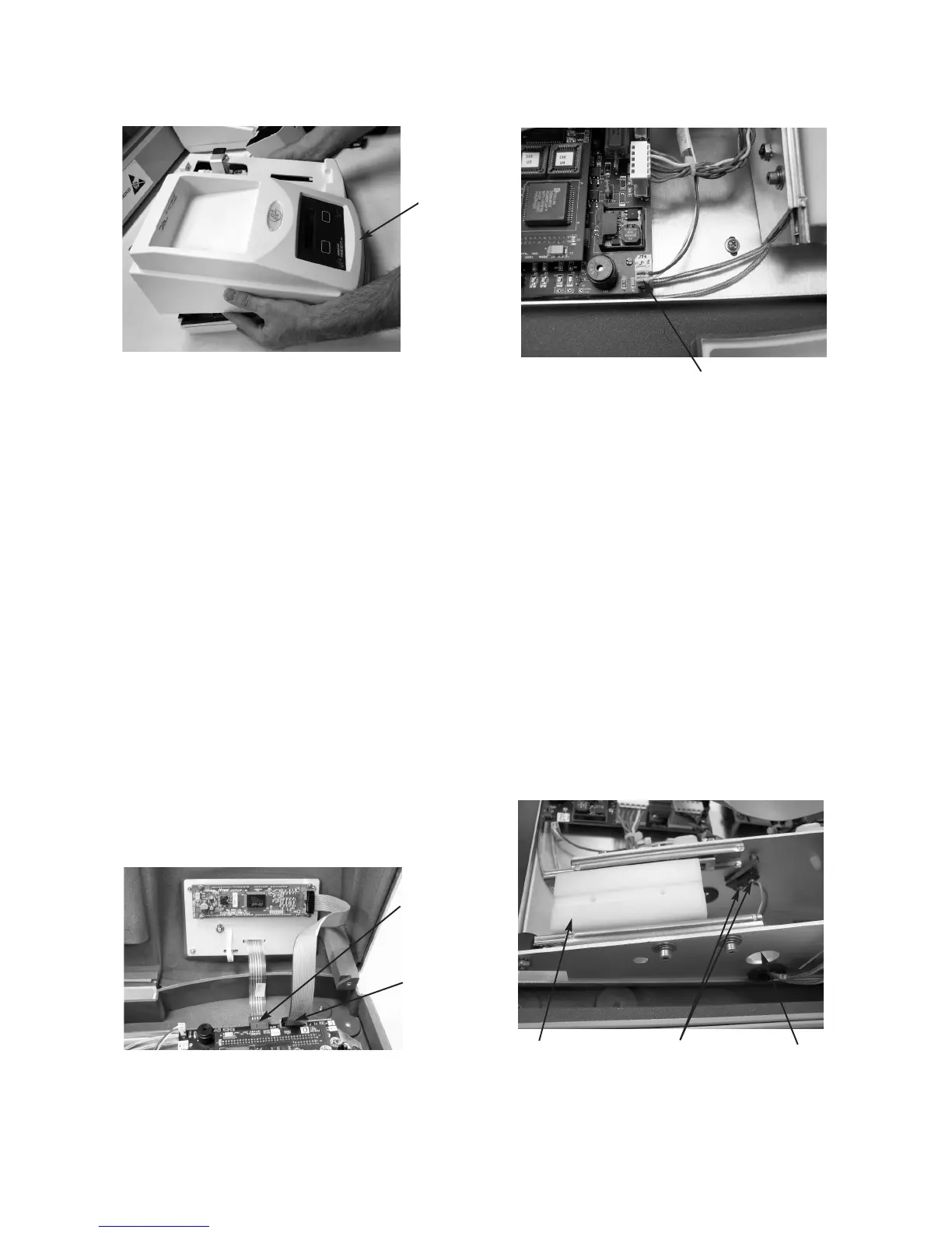
7. Unplug the actuator switch cable (G) from
connector J1 of the circuit board assem-
bly.
8. Make sure that the slide plate (H) is
pushed all the way toward the front of the
instrument.
9. Insert a small cross-point screwdriver
through the access hole (I) in the right
side of the sample handling assembly
bracket to engage screws (J) holding the
switch assembly. Use a 3/16-inch nut
driver or wrench to remove the two nuts
securing the switch assembly. Remove
the two screws and the switch assembly,
pulling the cable through the access hole
in the left side of the sample handling
assembly bracket.
10. Pass the end of the replacement switch
cable through the access port in the left
side of the sample handling assembly
bracket. Replace the actuator by rein-
stalling the two sets of screws, lock wash-
ers and nuts.
11. Plug the actuator switch cable (G) into
connector J1 of the circuit board assem-
bly.
H
I
J
D
G
E
F