332P140 Rev1
(3325 Service Manual)
Page 2 of 2
Note: Use caution when separating the top
and bottom covers to avoid damaging
the display and keypad cable connec-
tions.
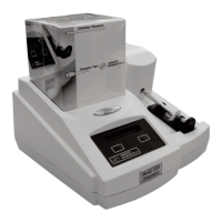
5. Return the instrument to its upright posi-
tion and carefully rotate the rear of the
cover up and away from the bottom cover
while keeping the front portion close to
the bottom cover (D).
6. Unplug the keypad cable (E) and the dis-
play cable (F) from the connectors on the
circuit board assembly, and remove the
instrument cover.
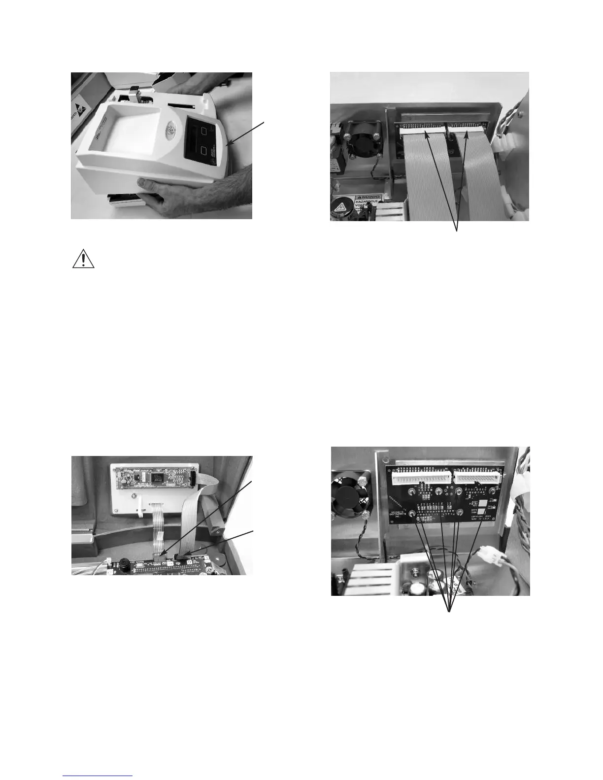
7. Disconnect the two ribbon cables (G)
from the connectors on the rear panel cir-
cuit board.
8. Remove the I/O circuit board (six screws)
(H).
9. Install the new I/O board. Make sure that
all screws are tightened securely to pro-
vide proper electrical grounding (earth-
ing).
10. Reassemble the instrument by reversing
steps 1 - 7, noting the proper pin 1 orien-
tations for all cable assemblies and their
connectors.
G
H
D
E
F