332P340 Rev1
(3325 Service Manual)
Page 2 of 2
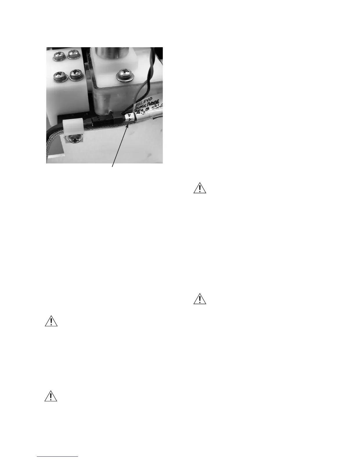
5. Cut the cable tie (E) securing the block
probe to the cooling well housing.
Carefully pull out the old probe.
6. Inject thermal grease into the far end of
the hole for the block probe. Slide the
new probe slowly into the hole until it
will not go any farther. Take care not to
damage the probe.
7. Bend the block probe cable and secure it
to the sample well housing using a cable
tie (E). Make sure that it is positioned so
that it will fit within the slot in the sample
probe spacer.
Note: On some instruments, the spacer has
been integrated into the sample well
housing.
8. Note the bin number of the block probe
(F).
9. Reinstall the sample probe spacer and
sample probe.
Note: The spacer may not be present on all
instruments. It has been integrated
into the sample well housing.
10. Add Loctite 222 thread lock (or equiva-
lent) to the two standoffs securing the
sample probe. Install the standoffs (D)
and tighten each using the following
sequence to avoid damaging the sample
probe or cooling well housing:
a. Tighten both standoffs finger-tight.
b. Using a 3/16-inch nut driver or
wrench, tighten each standoff 1/2
turn.
c. Tighten each standoff an additional
1/4 turn.
The sample probe should be tight, with a
slight bow.
Note: The spacer and the probe may be
touching each other, or there may be a
small gap between the two parts.
Either condition is acceptable.
However, no gap is allowed between
the standoffs and the probe. The spac-
er may not be present on all instru-
ments. It has been integrated into the
sample well housing.
11. Plug the sample probe cable connector
(B) into the sample probe. Plug the block
probe cable connector (C) into the block
probe.
Note: If the bin number (F) for the new
block probe is different from that for
the old probe, restart the instrument
and reset the bin value to the new
number.
12. Reinstall the solenoid cover.
13. Plug in the instrument and turn on the
power. Verify proper block probe bin
number and recalibrate, if required.
F