332P620 Rev2
(3325 Service Manual)
Page 2 of 3
E
F
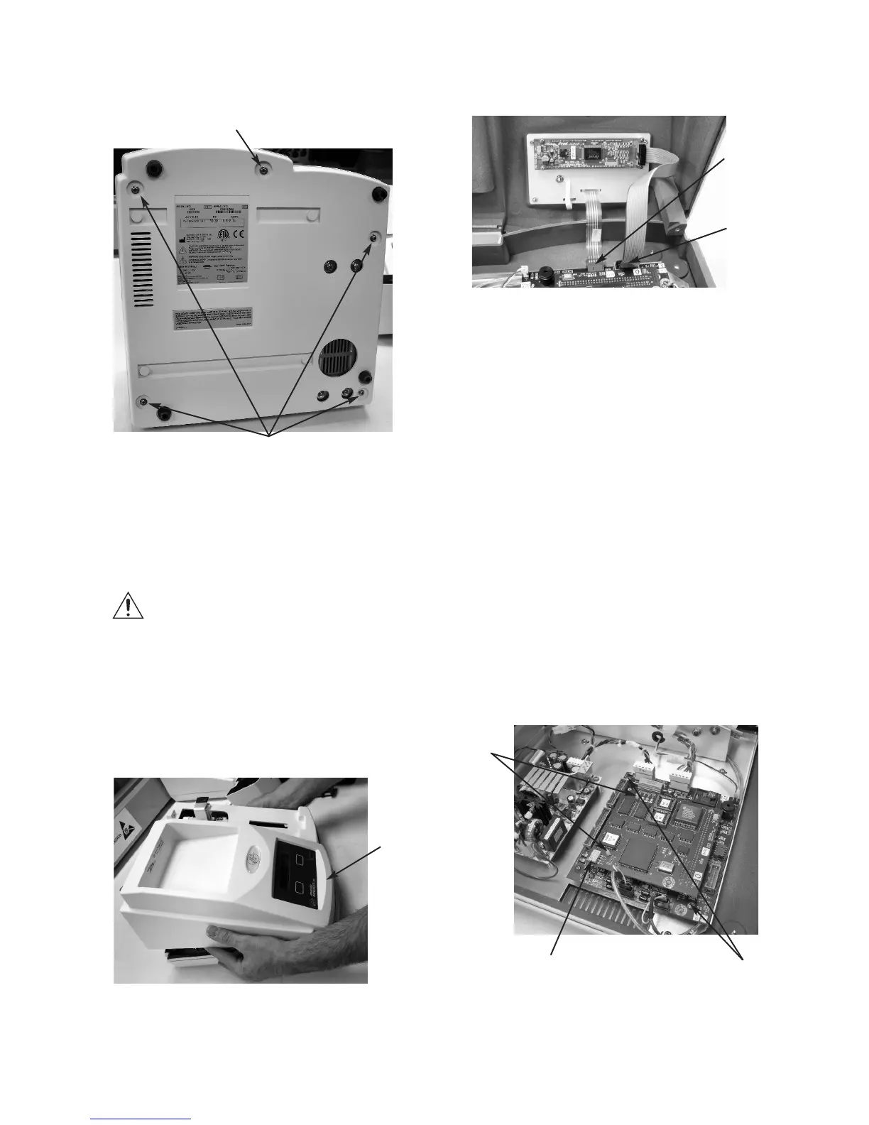
6. Unplug the keypad cable (E) and the dis-
play cable (F) from the connectors on the
circuit board assembly, and remove the
instrument cover.
7. Disconnect the two ribbon cables from
the application board.
8. To remove the PCB120 central proces-
sor board only, use pliers to squeeze the
tabs on the two plastic standoffs (G) and
pull the PCB120 board away from the
PCB115 board. Separate the boards care-
fully to prevent damaging the connector
pins.
9. To remove the PCB115 application
board or the complete circuit board
set, disconnect all cables from the board.
Remove the two screws (H) securing the
PCB115 application board. Lift the board
off of the two press-fit standoffs.
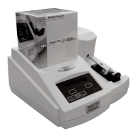
4. Carefully tip the instrument to rest on the
back panel and remove the five screws
(C) securing the top cover.
Note: Use caution when separating the top
and bottom covers to avoid damaging
the display and keypad cable connec-
tions.
5. Return the instrument to its upright posi-
tion and carefully rotate the rear of the
cover up and away from the bottom cover
while keeping the front portion close to
the bottom cover (D).
G
H
I
D
C
C (Some units may not have this screw.)