332P149 Rev1
(3325 Service Manual)
Page 2 of 2
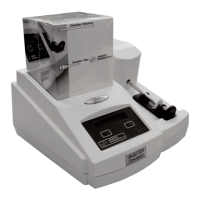
while keeping the front portion close to
the bottom cover (D).
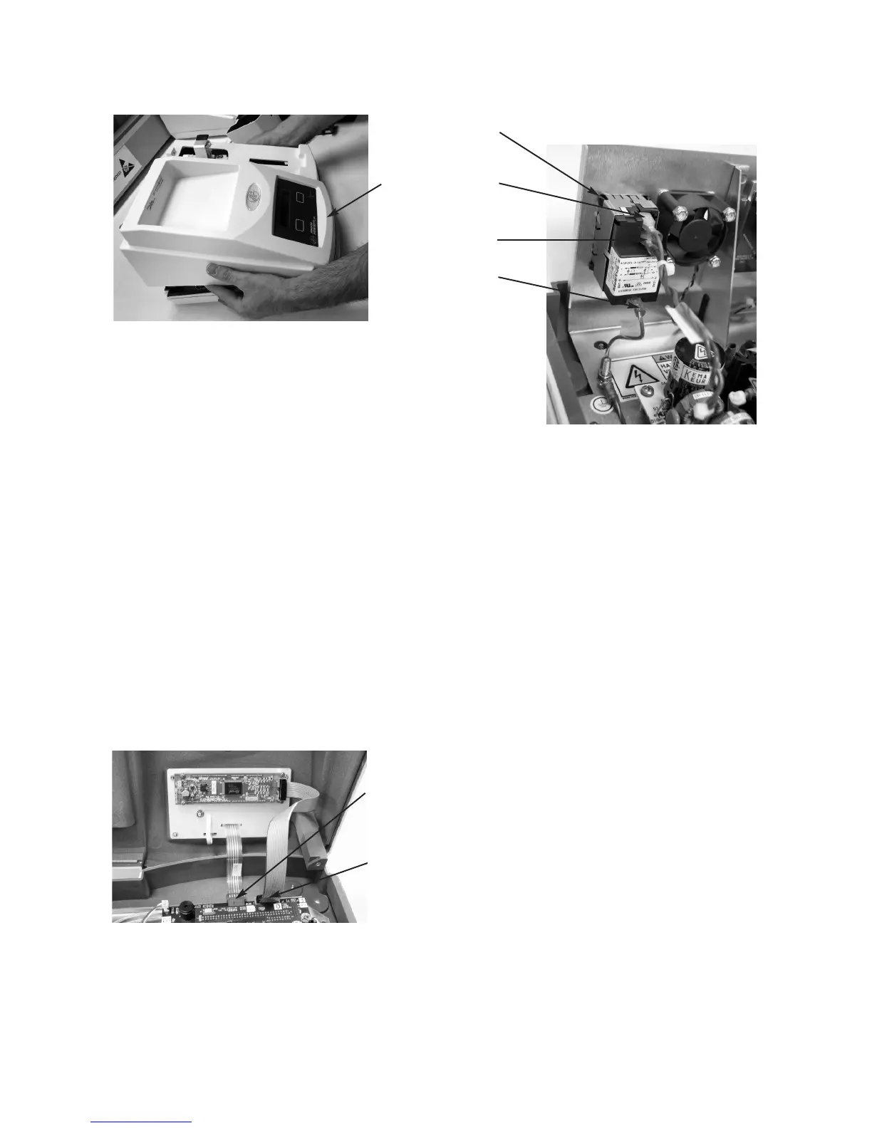
6. Unplug the keypad cable (E) and the dis-
play cable (F) from the connectors on the
circuit board assembly, and remove the
instrument cover.
7. Disconnect the brown lead (G) from the
top terminal of the power entry module.
Disconnect the blue wire (H) from the
middle terminal. Disconnect the ground
wire (I) from the lower terminal.
8. Using a flat-bladed screwdriver, compress
each of the five locking tabs (J) securing
the power entry module in the chassis,
while pushing on the module. Once all
tabs have been pushed through the chassis
opening, remove the power entry module.
9. Insert the new power entry module into
the opening. Push it firmly into place to
seat all five locking tabs. A distinct click
should be heard when the tabs lock in
place. Carefully inspect the module to
ensure that all five tabs are properly
engaged.
10. Insert a flat-bladed screwdriver into the
recesses between the fuse holder and the
old power entry module. Carefully pry
open the fuse holder and remove it from
the power entry module.
11. Install the fuse holder and fuses in the
new power entry module. Make sure that
the fuse holder is fully seated in the
recess.
12. Reassemble the instrument by reversing
steps 1 - 7, noting the proper pin 1 orien-
tations for all cable assemblies and their
connectors.
H
I
G
J
D
E
F