332P700 Rev2
(3325 Service Manual)
Page 2 of 2
D
c. Tighten each standoff an additional
1/4 turn.
The sample probe should be tight, with a
slight bow.
Note: The spacer and the probe may be
touching each other, or there may be
a small gap between the two parts.
Either condition is acceptable.
However, no gap is allowed between
the standoffs and the probe. The spac-
er may not be present on all instru-
ments. It has been integrated into the
sample well housing.
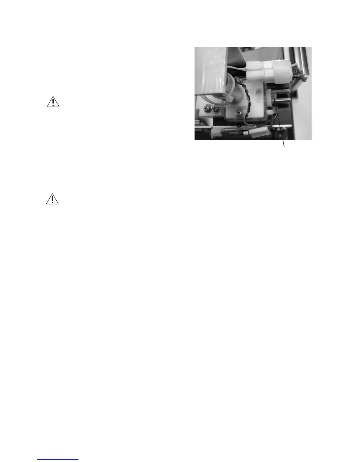
7. Plug the sample probe cable connector
into the sample probe (B).
Note: If the bin number (D) for the new
sample probe is different from that for
the old probe, restart the instrument
and reset the bin value to the new
number.
8. Reinstall the solenoid cover.
9. Plug in the instrument and turn on the
power. Run four probe bin tests to deter-
mine the resistance and bin number of the
sample probe. The resistance obtained
during the last three probe bin tests
should be within 2 ohms of each other.
Using the bin number displayed at the
completion of the last probe bin test,
reset the sample probe bin number and
recalibrate (see User’s Guide for proce-
dure).
If the resistance values obtained during
the last three probe bin tests exceeds 2
ohms of each other, replace the sampler
plunger wire (part number 3M0828) and
repeat the sample probe bin tests.