332P087 Rev2
(3325 Service Manual)
Page 2 of 3
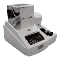
6. Unplug the keypad cable (E) and the dis-
play cable (F) from the connectors on the
circuit board assembly, and remove the
instrument cover.
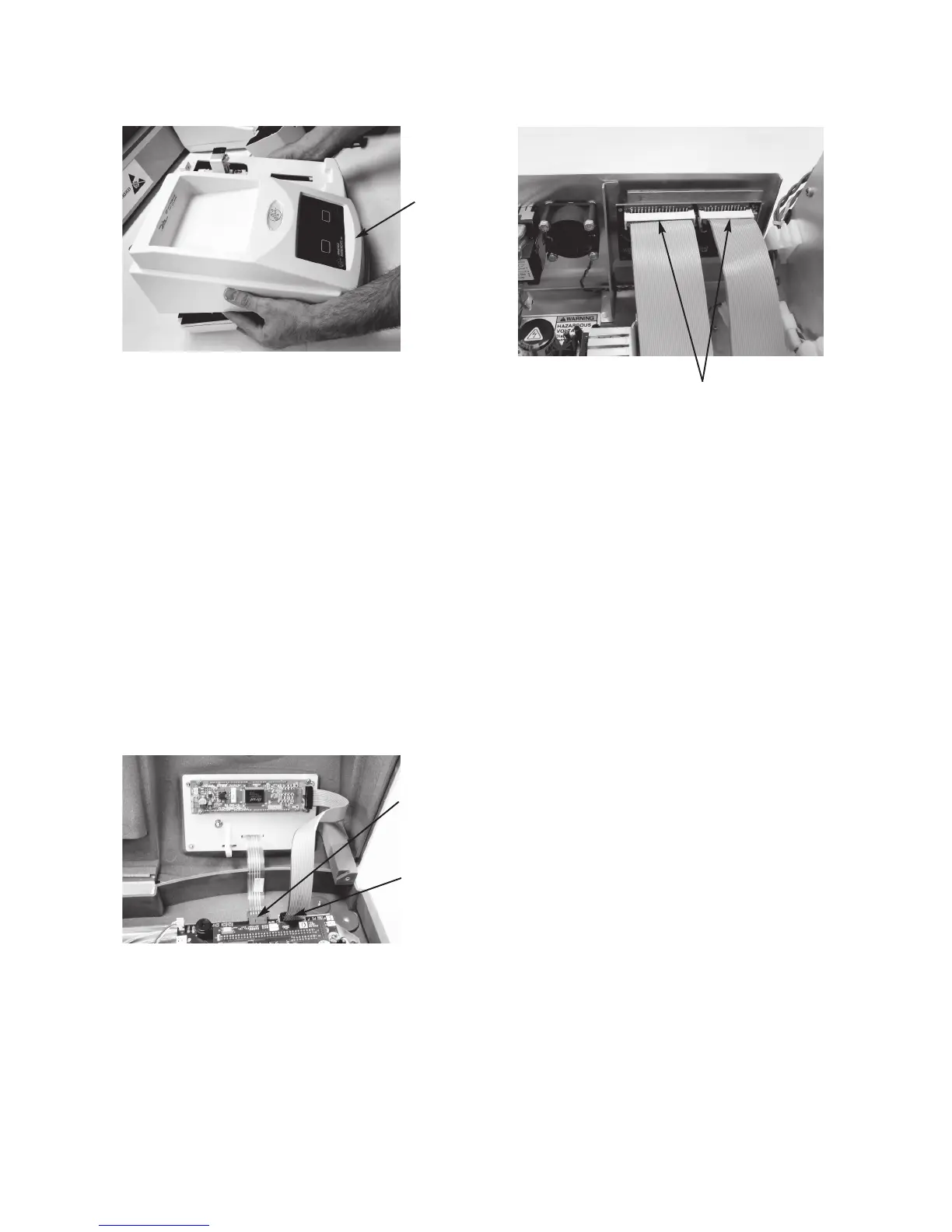
7. Disconnect the two ribbon cables (G)
from the connectors on the rear panel cir-
cuit board.
8. Disconnect the fan assembly connector
(H) from the power supply wiring har-
ness.
9. Remove the two screws (I) securing the
fan assembly resistor, if equipped, and the
four nuts (J) securing the fan to the chas-
sis.
10. Remove the fan from the mounting studs
and carefully pull the resistor, if equipped,
and the connector through the opening in
the chassis bracket.
11. Carefully route the connector of the new
fan assembly through the opening in the
chassis bracket.
12. Reassemble the instrument by reversing
steps 1 - 9, noting the proper pin 1 orien-
tations for all cable assemblies and their
connectors.
Note: Fan assemblies manufactured after
July 2015 no longer use a chassis-
mounted resistor. If replacing an
assembly with a chassis-mounted
resistor, the two screws may be dis-
carded.
G
E
F
D