EasyManua.ls Logo

Advantage Controls MegaTronMT User Manual

Advantage Controls MegaTronMT
40 pages
To Next Page IconTo Next Page
To Previous Page IconTo Previous Page
Page #5 background image
5
Pre-Wired
Pre-wired units are supplied with a 16 AWG cable(s) with 3-wire grounded USA 115 volt plug for incoming
power and 3-wire grounded receptacle cords for all control relay outputs also 16 AWG.
Conduit
Conduit units are predrilled at the factory and supplied with conduit knockouts for easy hard wiring to supplied
detachable connectors on the relay card(s) located in the lower section of the controller. Remove the screws
of the lower panel for access.
NOTES:
1. Do not drill holes in upper section of enclosure.
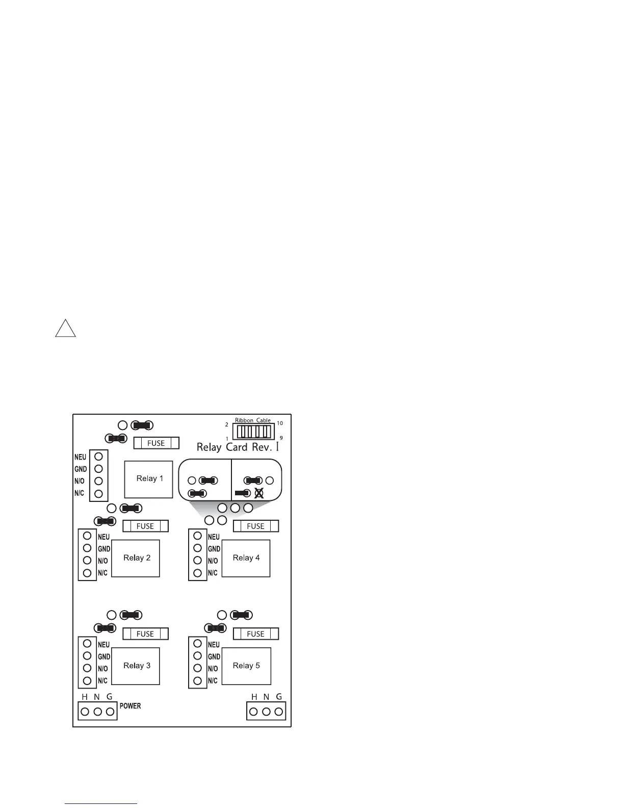
2. All relays provide a N.O. and N.C. output.
 7KHFRQWUROIXQFWLRQWKDWDFWLYDWHVHDFKUHOD\RXWSXWLVSUHFRQ¿JXUHGDWWKHIDFWRU\
based on the options selected. To change relay activation, see on page 30.
4. See page 34 for common bleed / blowdown valve wiring.
 5HIHUWRODEHOLQVLGHORZHUSDQHOFRYHUIRUVSHFL¿FUHOD\ERDUGFRQ¿JXUDWLRQVXSSOLHG
 5HOD\VFRQ¿JXUHGDV³GU\FRQWDFW´VKRXOGRQO\KDYH'&YROWDJHUDQWKURXJKWKHP7KH*1'
FRQQHFWLRQSRLQWUHSODFHVWKH1(8ZKHQFRQ¿JXUHGIRUGU\FRQWDFW([DPSOH8VH*1'DQG12
for a normally open dry contact relay output.)
WARNING:,IMXPSHUVDUHQRWFRQ¿JXUHGIRUGU\FRQWDFWOLQHYROWDJHZLOOEHVXSSOLHG
Relay Card Wiring
Rev. I Relay Card
!
Powered relay Dry contact
INPUT

Other manuals for Advantage Controls MegaTronMT

Question and Answer IconNeed help?

Do you have a question about the Advantage Controls MegaTronMT and is the answer not in the manual?

Advantage Controls MegaTronMT Specifications

General IconGeneral
BrandAdvantage Controls
ModelMegaTronMT
CategoryController
LanguageEnglish

Summary

Introduction to MegaTronMT Controllers

MegaTronMT Model Numbering System

Explains how to determine unit features by comparing the model number to tables.

MegaTronMT Unit Description

Provides a general overview of the controller's capabilities and applications.

MegaTronMT Control Functions

Details the core control functions including conductivity, pH, and ORP.

Chemical Feed Timers Overview

Types of Chemical Feed Timers

Describes the various programmable timer types like Pulse, Limit, Recycle, and 28-Day.

Installation and Wiring

Electrical Wiring Guidelines

Covers incoming power, relay outputs, and essential safety warnings for wiring.

Pre-Wired Unit Specifications

Details the specifications and cables provided for pre-wired units.

Conduit Unit Wiring

Describes the process and considerations for wiring conduit units.

Relay Card Wiring Diagram

Illustrates the connections for the relay card, including powered and dry contact.

System Connections

MegaTronMT Back Pane Connections

Diagrams showing power, communication, and relay outputs on the back pane.

System Card Connection Diagrams

Illustrates wiring for Standard and RTD Boiler System Cards.

4-20mA Signal Configuration

4-20mA Output Card Wiring

Details wiring for isolated and non-isolated 4-20mA outputs.

4-20mA Input Card Wiring

Explains the requirements for 4-20mA input signals and voltage.

Mounting and Electrode Installation

Mounting Instructions

Guidance on selecting a mounting location and associated warnings.

Cooling Tower Electrode Installation

Specific instructions for installing electrodes in cooling tower systems.

Boiler Installation Guidelines

Boiler Electrode Installation

Instructions for mounting and installing electrodes in boiler systems.

Boiler Conductivity Electrode Wiring

Details wiring for specific boiler conductivity electrodes (BE-4RTD, BE-32).

Front Panel Interface

MegaTronMT Front Panel Overview

Description of the controller's display, buttons, and status indicators.

System Operation and Calibration

System Operation Modes

Explains the RUN and SET-UP modes of controller operation.

Typical Start-Up Procedures

Steps to follow before initiating the controller start-up procedure.

Probe Calibration Procedures

Guides for calibrating conductivity, pH, and ORP probes.

Menu Navigation and Settings

Controller Home Menu Navigation

Explains how to navigate through the controller's menu structure.

Setting Control Parameters (Set Points)

Details on setting relay set points for analog probe readings.

Conductivity Set Point Options

Configuration of set points, differential, and alarms for conductivity.

pH and ORP Set Point Configuration

Settings for pH and ORP set points, including interrupt and secondary set points.

Advanced System Configurations

Boiler Conductivity Sampling Methods

Describes Timed Sampling, Sample and Hold, and Continuous methods for boilers.

Auxiliary Input and Alarm Settings

Configuration of digital inputs for flow switches and alarm display options.

Calibration Procedures

General Calibration Process

Steps for adjusting displayed probe readings to match testers or known solutions.

Conductivity Calibration Details

Specific procedures for calibrating conductivity using calibrate or reset zero.

pH and ORP Calibration Methods

Explains 1-point and 2-point calibration procedures for pH and ORP.

Timer Functionality

Timer Types and Setup

Overview of timer functions and initial setup screens.

Pulse Timer Configuration

Detailed setup for pulse timers, including accumulation and meter input.

Specific Timer Configurations

Recycle Timer Settings

Configuration options for the Recycle timer (ON/OFF cycles).

Post Bleed Timer Settings

Parameters for the Post Bleed timer, including % of source and limit time.

With Bleed Timer Settings

Configuration for the timer that runs with bleed, including limit time.

Advanced Timer and Alarm Settings

28-Day Timer Programming

Details on programming the 28-Day timer with weeks, days, and feed locks.

Alarm Status and Access

How to view current alarms and access the alarm list from Setup/Run.

Water Meter and Signal Management

Water Meter and Totalizer Setup

Configuration of water meter inputs, units, and totalizers.

Auxiliary Flowmeter Inputs (Option W)

Details on using auxiliary flowmeter inputs for tracking and alarms.

mA Signal Configuration Overview

Introduction to mA signal settings, including output and input configurations.

4-20mA Signal Configuration Details

4-20mA Output Configuration

Setting up 4-20mA outputs, defining signal source and values.

4-20mA Input Configuration

Setting up 4-20mA inputs, including set points and alarms.

4-20mA Output Calibration

Calibrating 4-20mA outputs to ensure accurate signal transmission.

4-20mA Input Calibration

4-20mA Input Calibration Process

Calibrating 4-20mA inputs to match external device signals.

Customization and Configuration

General Customize Menu Options

Setting unit names, relay names, system names, and input units.

Notepad Functionality

Using the notepad for custom data entry and reminders.

mA Input Naming and Units

Naming and setting units of measurement for mA inputs.

Controller Configuration Settings

Run Screen Customization

Customizing the display of information on the RUN screen.

Configure Menu Access

Accessing menus for passwords, relays, date/time, and system info.

Password Management

Setting administrator and user passwords for system access.

System Settings and History

Date and Time Configuration

Setting the controller's date, time, day, and week.

Relay Configuration and Logic

Choosing main actions, activators, and disablers for relay control.

History Logging Settings

Configuring history interval, water meter hour, and alarm delay.

Network and System Information

Flow Switch Input Settings

Configuring flow switch logic (open/closed) and timer behavior.

Temperature Scale Selection

Choosing between Celsius and Fahrenheit for temperature display.

Network Communication Settings

Viewing and setting up network parameters for remote communication.

System Information Display

Viewing firmware version and controller serial number.

Data Logging and Review

Viewing Historical Data Logs

Accessing relay, alarm, sensor, event, and notepad history.

Notepad Entry Review

Entering and reviewing manually entered data in the notepad.

Water Meter Historical Data

Reviewing hourly and daily water meter history data.

Flow Meter Setup

Auxiliary Flow Meter Configuration

Setting up auxiliary flow meter inputs, including pulse value and tracking.

Relay Status and Control

Viewing Relay Status

Displays accumulated ON times, custom names, and current status of relays.

Maintenance Procedures

Conductivity Electrode Cleaning

Step-by-step guide for cleaning conductivity electrodes.

pH and ORP Electrode Cleaning

Procedures for cleaning pH and ORP electrodes and restoring response.

Troubleshooting Guide

Common Symptoms and Solutions

A chart to identify problems like false readings or no power and their solutions.

Product Information and Warnings

Advantage Controls Product Warranty

Details the warranty coverage and limitations for control systems.

30 Day Billing Memo Policy

Explains the factory exchange program for uninterrupted service.

FCC Radio Frequency Warning

Notice regarding potential radio frequency interference and compliance.

Boiler Blowdown Valve Wiring

LD2 Wiring for MegaTron MT

Wiring diagrams for common boiler blowdown valve connections.

Specialized Wiring Diagrams

Pyxis Fluorometer Wiring

Wiring instructions for connecting a Pyxis Fluorometer to the MegaTron MT.

Autorol Turbine Meter Wiring

Wiring information for Autorol Turbine Meters with MegaTron MT.

Building Management System Wiring

CABLE-7P-2A Nano-M to MegaTronMT Wiring

Wiring a Nano-M to a MegaTronMT or other Building Management System.

Related product manuals