AIMb-763 1-25
1.10.3 Internal connectors
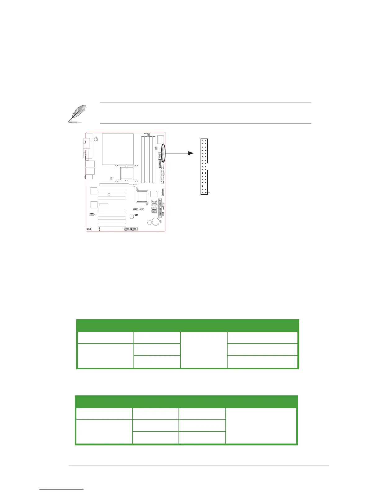
1. Floppy disk drive connector (34-1 pin FLOPPY)
This connector is for the provided oppy disk drive (FDD) signal cable. Insert
one end of the cable to this connector, then connect the other end to the
signal connector at the back of the oppy disk drive.
Pin 5 on the connector is removed to prevent incorrect cable connection when
using an FDD cable with a covered Pin 5.
2. Primary IDE connector (40-1 pin PRI_IDE)
These connectors are for Ultra DMA 133/100/66 signal cables. There are three
interfaces on each Ultra DMA 133/100/66 signal cable: blue, black, and gray.
Connect the blue interface into the motherboard’s IDE connector, then select one
of the following modes to congure your hard disk drive(s).
Cable Select Mode - use this mode to select the operating mode by
cable connectors.
No. of drives Drive type Drive jumper Cable connector
1 With OS
Cable select
black
2
With OS black
Without OS gray
Jumper Select Mode - use this mode to select the operating mode by
hard disk drive jumper.
No. of drives Drive type Drive jumper Cable connector
1 With OS Master
black or gray
2
With OS Master
Without OS Slave
NOTE: Orient the red markings on
the floppy ribbon cable to PIN 1.
Floppy disk drive connector
PIN 1
FLOPPY
NOTE: Orient the red markings on
the floppy ribbon cable to PIN 1.
Floppy disk drive connector
PIN 1
FLOPPY