EKI-1221/1222/1224 User Manual 18
2.3.2 Connecting Power
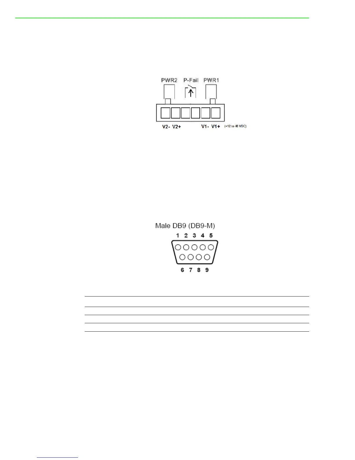
The EKI-1221/1222/1224 supports dual +12 to 48 VDC power inputs and a power-fail
relay output. Following figure is the power terminal block pin assignments. Please
refer it to connect to the proper power requirements and polarity.
Figure 2.18 Power Connector
You can connect an alarm indicator, buzzer or other signaling equipment through the
power-fail relay output. The relay opens if power input V1 or V2 fails. (“Open” means
if you connect relay output with an LED, the light will be shut off)
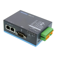
2.3.3 Connecting Serial Devices
The EKI-1221/1222/1224 provides one, two or four standard serial ports DB9 (male)
connectors. RS-232/422/485 pin assignments are as below.
Figure 2.19 EKI-1221/1222/1224 Serial Port Pin Assignments
2.3.4 Connecting to a Host or the Network
The EKI-1221/1222/1224 provides two RJ45 connectors with dual independent
Ethernet networks, and supports 10/100 Mbps transmission speed. The EKI-1221/
1222/1224 will auto detect current transmission speed on the network and configure
itself accordingly. For normal operation, the EKI-1221/1222/1224 can be connected
to other hubs or switches through a twisted-pair straight through the Ethernet cable.
For configuration or troubleshooting purposes, user may need to connect the EKI-
1221/1222/1224 directly to the host PC. In this operation mode, user can use a
crossover Ethernet cable to connect the EKI-1221/1222/1224 to the host PC’s
Ethernet connector.
Pin123456789
RS-232 DCD RX TX DTR GND DSR RTS CTS RI
RS-422 TX- - - TX+ GND - RX+ - RX-
RS-485 Data- - - Data+ GND - - - -