21 SPC-800(M) User Manual
Chapter 2 System Setup
2.2 System Setup
SPC-800(M) devices install Cover IO
1. The Base Unit standard product contains SPC-800 device, Cover IO and ARM
screws.
Fix 2 pcs with M5 x 10 screws on the Cover IO screw hole location (Do not fas-
ten screw)
2. Place Cover IO to product and fasten 2pcs Screws.
3. Fix 2 pcs with M5 x 10 screws on the other Cover IO screw hole location
The following figure shows an example.
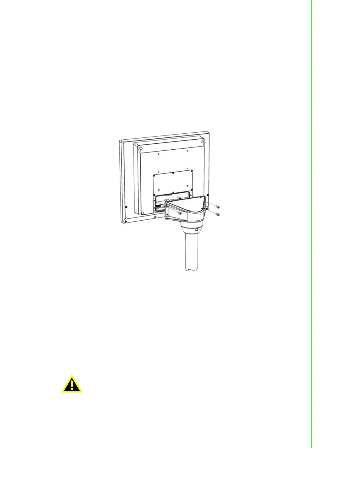
2.3 Mounting the SPC-800(M) device
The section describes the mounting of the device to a support ARM or VESA system
using example figures.SPC-815 and SPC-821 are the same design and same com-
ponent for Pendant and Pedestal mounting.(no additional component is needed) And
VESA mount is optional. We use icoteck German vendor for Cable Entry and design
100 x 100mm standard VESA compliant hole to allow wall and accessory mounting
option.
Warning!
Make sure that fasteners are adequately dimensioned during installa-
tion. Make sure to consider the weight of the device and the forces act-
ing on the device when dimensioning.
Inadequately dimensioned fasteners or insufficient lock may cause the
device to fall down. Serious physical injury may result.
The device must be mounted securely.