25 UNO-2483G/2473G User Manual
Appendix A System Settings and Pin Assignments
A.2 Board Connectors and Jumpers
There are several connectors and jumpers on the UNO-2483G/UNO-2473G board.
The following sections tell you how to configure the UNO-2483G/UNO-2473G hard-
ware setting.
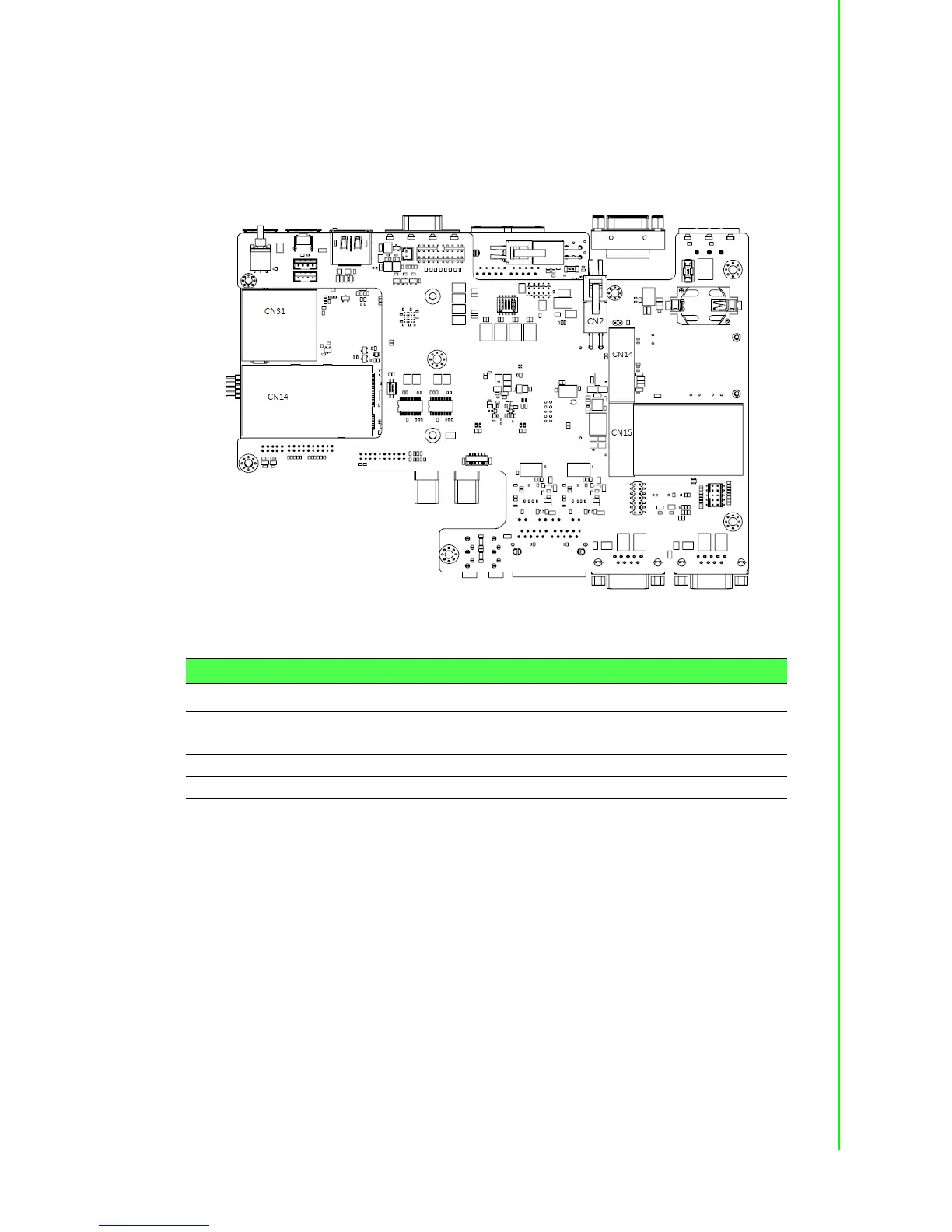
Figure A.1 shows the locations of the connectors and jumpers.
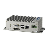
Figure A.1 UNO-2483G Connector & Jumper Locations (front)
Figure A.2 shows the locations of UNO-2473G’s connectors and jumpers.
Table A.2: Connectors and Jumpers
Label Function
CN14 CN15 PCI Express mini Card Socket
BH1 Battery for RTC
CN29 ON/OFF/RESET Switch
CN11 COM3, COM4