vii UNO-2483G/2473G User Manual
Contents
Chapter 1 Overview...............................................1
1.1 Introduction ............................................................................................... 2
1.2 Safety Precautions .................................................................................... 2
1.3 Accessories............................................................................................... 3
1.4 Optional Accessories ................................................................................ 3
1.5 Hardware Specifications ........................................................................... 3
Chapter 2 Hardware Functionality.......................5
2.1 Introduction ............................................................................................... 6
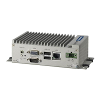
Figure 2.1 Front Panel of UNO-2483G ........................................ 6
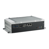
Figure 2.2 Rear Panel of UNO-2483G/UNO-2473G-E3AE ........ 6
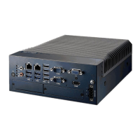
Figure 2.3 Front Panel of UNO-2473G-J3AE .............................. 6
Figure 2.4 Rear Panel of UNO-2473G-J3AE............................... 6
2.2 UNO-2483G/UNO-2473G Interface (COM1~COM4) ................................ 7
2.2.1 RS-232 Interface (COM 1 ~ 2)...................................................... 7
2.2.2 RS-422/485 detection ................................................................... 7
2.2.3 Automatic Data Flow Control Function for RS-485 ....................... 7
2.3 LAN: Ethernet Connector .......................................................................... 8
2.4 Power Connector ...................................................................................... 8
2.5 USB Connector ......................................................................................... 8
2.6 HDMI Display Connector........................................................................... 8
2.7 RTC Battery Specification ......................................................................... 9
Figure 2.5 RTC Battery Location ................................................. 9
2.8 Power Button/Power Management ........................................................... 9
2.9 Reset Button ............................................................................................. 9
2.10 HD Audio................................................................................................. 10
2.11 PCI Express Mini Card Socket................................................................ 10
Figure 2.6 UNO-2483G mPCIe Location ................................... 10
Figure 2.7 UNO-2473G-E3AE mPCIe Location......................... 11
Figure 2.8 UNO-2473G-J3AE mPCIe Location ......................... 11
Chapter 3 Initial Setup ........................................13
3.1 Inserting a mSATA .................................................................................. 14
3.2 Chassis Grounding.................................................................................. 14
Figure 3.1 Chassis Grounding Connection................................ 14
3.3 Connecting Power................................................................................... 14
3.4 Installing a Hard Disk .............................................................................. 15
3.5 Installing a Wireless LAN Card and Antenna .......................................... 16
Figure 3.2 UNO-2483G.............................................................. 17
Figure 3.3 UNO-2473G.............................................................. 17
3.6 BIOS Setup ............................................................................................. 18
3.7 AMT Configuration .................................................................................. 18
3.8 Teaming Configuration............................................................................ 20
3.9 Enabling RAID in BIOS ........................................................................... 22
Appendix A System Settings and Pin Assignments
23
A.1 System I/O Address and Interrupt Assignment ....................................... 24
Table A.1: Interrupt Assignments............................................... 24