79 USC-360 User Manual
Chapter 3 Hardware Installation
3.3.3 Install Scanner on IO Side
3.4 Guest Display Installation
3.4.1 10.1” 2nd Display Rear Mount installation
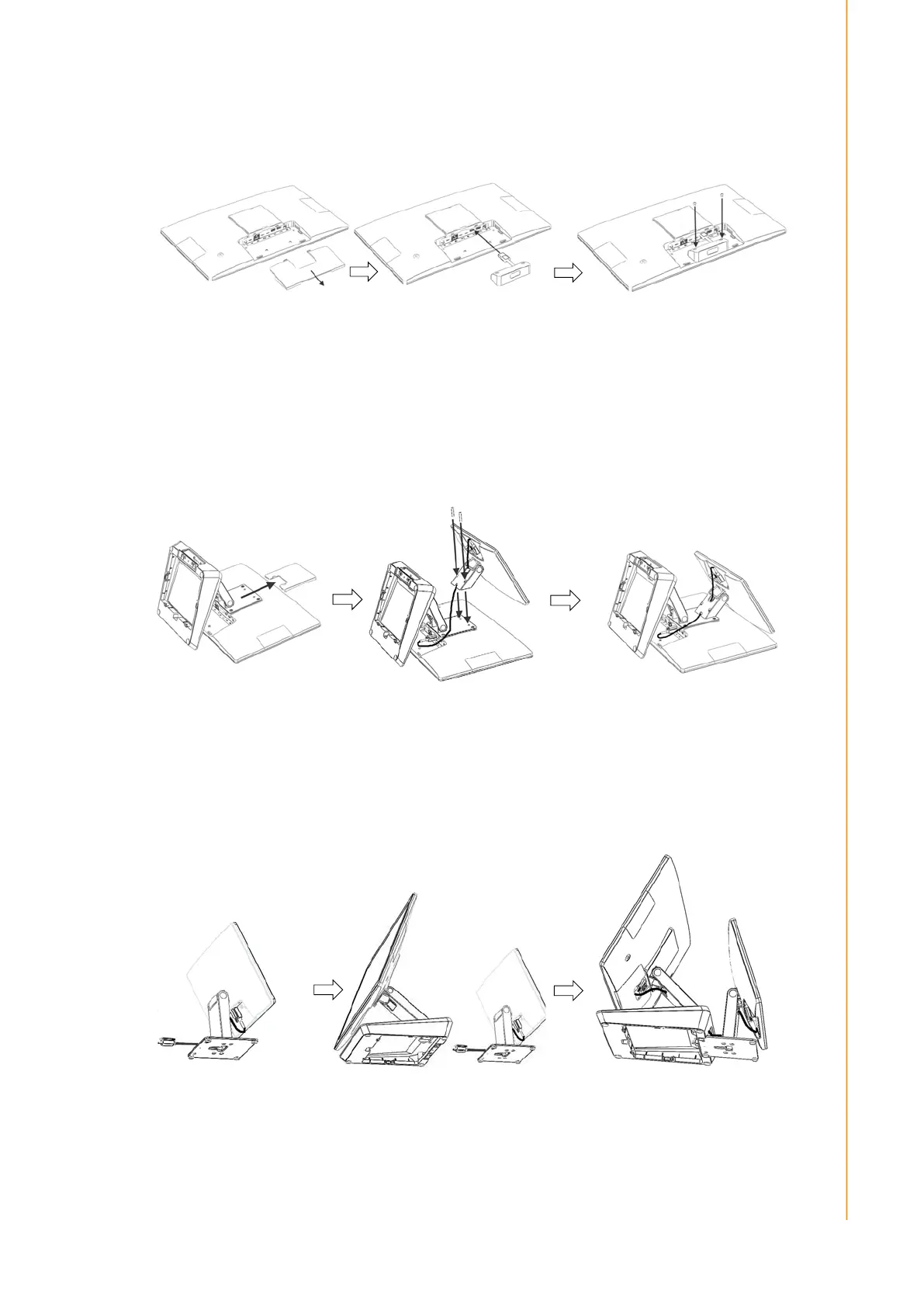
3.4.2 10.1” & 15.6” 2nd Display Installation
濦瀇濸瀃澳濅 濦瀇濸瀃澳濆
Remove peripheral cover in side
濦瀇濸瀃澳濄
Plug MSR /RFID module into
USB connector on the right
side.
Install the module and secure
with 2pcs screws (M3x4L).
濦瀇濸瀃澳濄 濦瀇濸瀃澳濅 濦瀇濸瀃澳濆
Remove VESA cover
and cable cover to
expose screw holes
Before attaching 10.1” display to the
rear of USC-360 with 2pcs screws
(M4*20L), need Type-C cable to
traverse rear mount bracket of 2nd
display.
Connect the other end of Type-C
cable to Type-C IO used for DP in
USC-360.
濦瀇濸瀃澳濄
濦瀇濸瀃澳濅
濦瀇濸瀃澳濆
Make Type-C cable
traverse the single
hinge stand of 2nd
display firstly.
Plug Type-C cable to Type-C
IO used for DP in USC-360.
Integrated 2nd display stand and
USC-360 stand with the hook
and hole in the stand base.