- 16 -
www.advateklights.com PixLite 16 Mk2 User Manual V210222
the DMX512 protocol operates is the RS485 electrical communications standard. This
is a differential transmission system consisting of a two-wire differential signal pair
and a ground connection. Ideally the differential signals should be wired into a
twisted pair cable. The D+, D- and ground connections are clearly labelled on the PCB
for the screw terminal connectors.
These outputs act as individual DMX512 universe outputs, effectively providing the
user with an E1.31 or Art-Net to 4 x DMX512 bridge (in addition to the normal pixel
outputs).
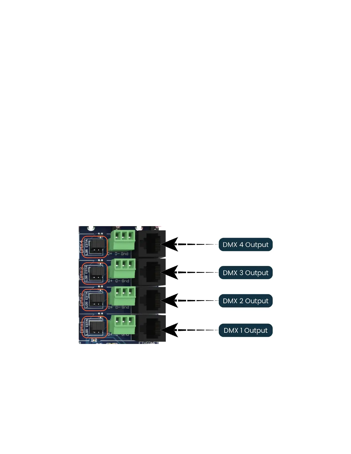
DMX512 signal data is also connected via the four vertical RJ45 sockets. On-board
jumper links (circled in Figure 8 below) allow each RJ45 DMX output to use either the
‘ESTA’ wiring or the ‘LOR’ wiring configuration. (All controllers are shipped with the links
in the ‘ESTA’ configuration.)
Please note that DMX outputs are not electrically isolated.
All these connectors and jumper links are located on the far right-hand edge of the
controller as shown in Figure 8 below.
Figure 8: Location of DMXOuputs
Below is the RJ45 socket pin-out for the DMX connectors when the “ESTA” wiring is
selected:
 Loading...