- 14 / 50 - BN 09 2671/01/01
+ BATT
- BATT
V
+
-
-
F13
+
-
LOAD
F1
+ BATT
- BATT
V
+
-
F14
+
-
LOAD
F1
5.2 SWITCHING ON
- Leave the positive side of the battery open, either through protective or opening device (e.g.
fuse F13: case 1 below) or through the battery cable not connected to the (+) BATT terminal of the charger (case
2 below).
- Close the negative side of the battery (-) (fuse, protective device, etc … ).
- Close the mains protective devices. Turn on the mains input and the rectifier.
The rectifier starts and the display shows:
V x.y.z = software version of the display controller
After a few seconds, the display shows:
Vxx.yy and aa.bb are the software versions of the
two micro controllers of the GCAU board
After a few seconds, the display shows the floating voltage and the rectifier current (at no-load).
NOTA: The current value can be around 0.5 A.
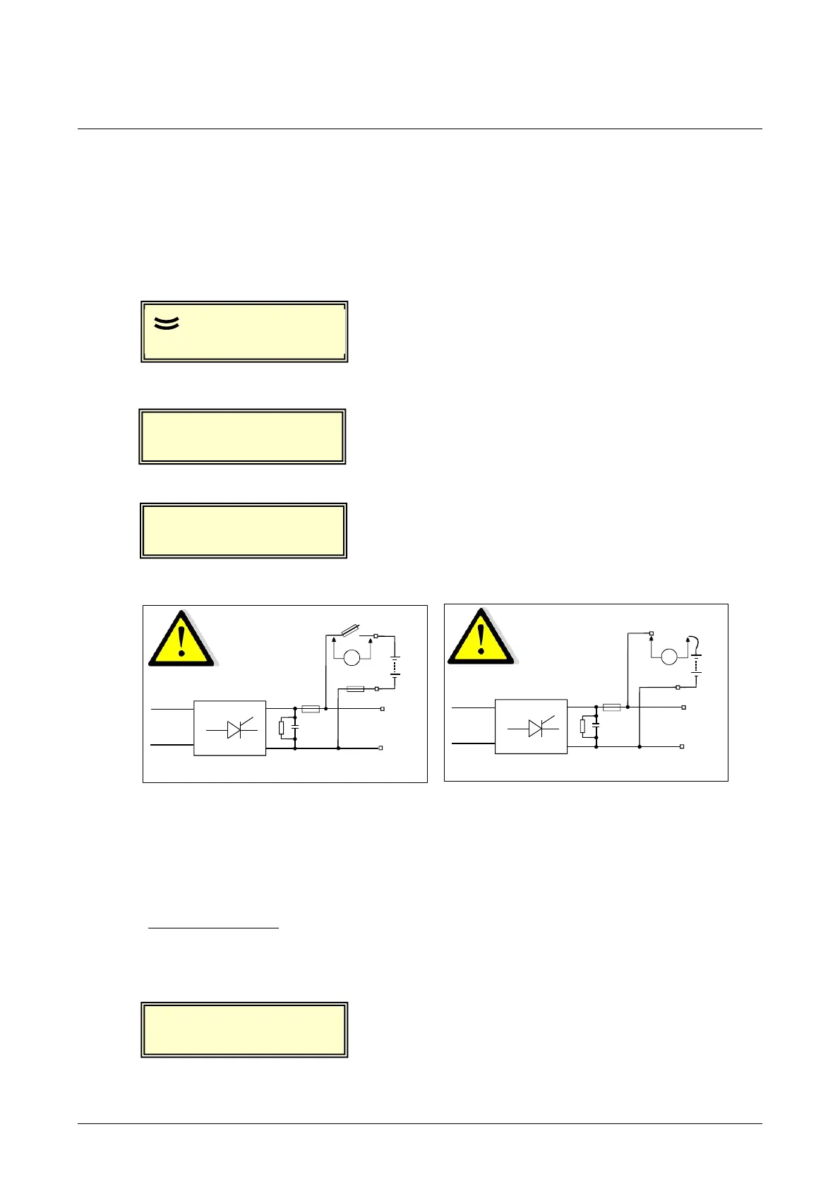
To check that the battery polarities are correct, take a voltage reading using a DC voltmeter as shown below:
- Case 1 - - Case 2 -
Configuration with battery fuse F13 Configuration without opening device
The voltage reading must not exceed 30% of the nominal voltage (refer to the customer drawings).
. If the voltage is outside of this tolerance, check the battery cables for correct polarity.
. If the voltage is correct, close fuse F13 or connect the battery (+) cable to the rectifier terminal. The rectifier
will charge the battery. During this operation, arcing may develop across the actuated device.
- Check that the displayed current increases (current to the battery).
AEG PS-GCAU
xx.
aa.bb
DC:xx.x
0.5A
Alarms:
DC:xx.x
3.0A
v x.y.z
 Loading...