- 6 / 50 - BN 09 2671/01/01
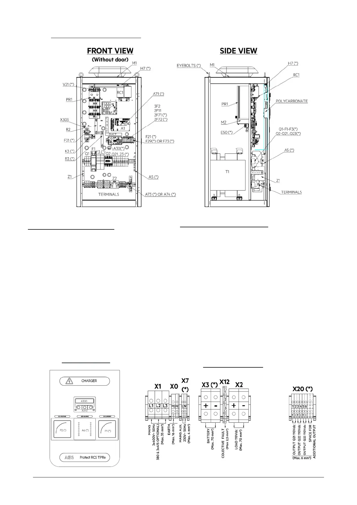
Charger internal layout description :
Charger standard components :
Input/output terminal block (X1-X2)
Mains input EMC filter (Z1) depending on
charger rating
Mains input breaker (Q1)
Mains input transformer (T1)
Rectifier bridge (PR1) – can be equipped with a
cooling fan depending on charger rating
Rectifier shunt (R2)
Rectifier output protection fuse (F1)
Filter capacitor (C1) with discharge resistor
Load output switch (Q2)
GCAU control card (A1)
Thyristor intarfe card (A2)
Cooling fan on some ratings (M1)
Common alarm terminal block (X12)
Charger options (marked with (*)
Analog rectifier output ammeter (P1)
Analog rectifier output voltmeter (P2-F21)
Front panel alarm LEDs (A6)
8 relays alarm card (A5)
RS485 modbus communication (A71)
TCP/IP communication for SNMP or Modbus over IP (A73)
IEC61850 communication (A74)
Internal DC power supply (A30) to energize
communication options
Internal lighting (H7) protected by F71, connected on X7
Anti-condensation heater (E50) protected by F72,
connected on X7
Blocking diode for paralleling (V21)
3x outgoing feeders (Q21-Q22-Q23) connected on X20
Battery output (X3-F3-K3-R3)
Battery temperature sensor with 5m cable (SD1)
Lifting eyes M10 – Qty 2
Front door details
Terminal block details
 Loading...