Ground Resistance Tester Models 3711 and 3731
- 26 -
Pad Mounted Transformer
Observe all safety requirements - High voltage may be present!
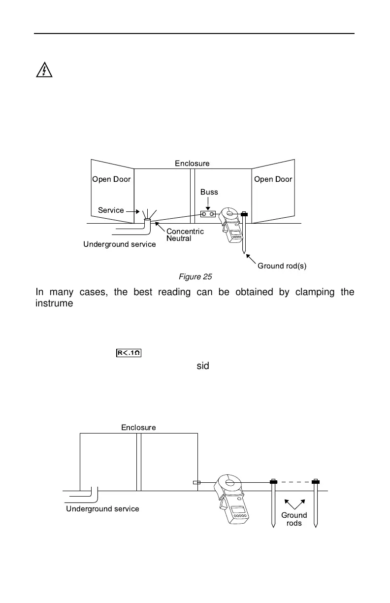
Locate and number all rods (usually only a single rod is present). If the
ground rods are inside the enclosure, refer to Fig. 25 and if they are
outside the enclosure, refer to Fig. 26. If a single rod is found within the
enclosure, the measurement should be taken on the conductor just
before the bond on the ground rod. Often, more than one ground
conductor is tied to this clamp, looping back to the enclosure or neutral.
Figure 25
In many cases, the best reading can be obtained by clamping the
instrument onto the ground rod itself, below the point when the ground
conductors are attached to the rod, so that you are measuring the
ground circuit. Care must be taken to find the conductor with only one
return path to the neutral.
Generally < 0.7Ω
R
.1
indicates that you are on a closed loop. In Fig.
26, the ground rod is located outside the enclosure. Clamp at the
indicated measuring point to obtain the correct reading. If more than one
rod exists at different corners of the enclosure, it is necessary to
determine how they are connected to properly measure the ground
resistance.
Figure 26