Figure 12
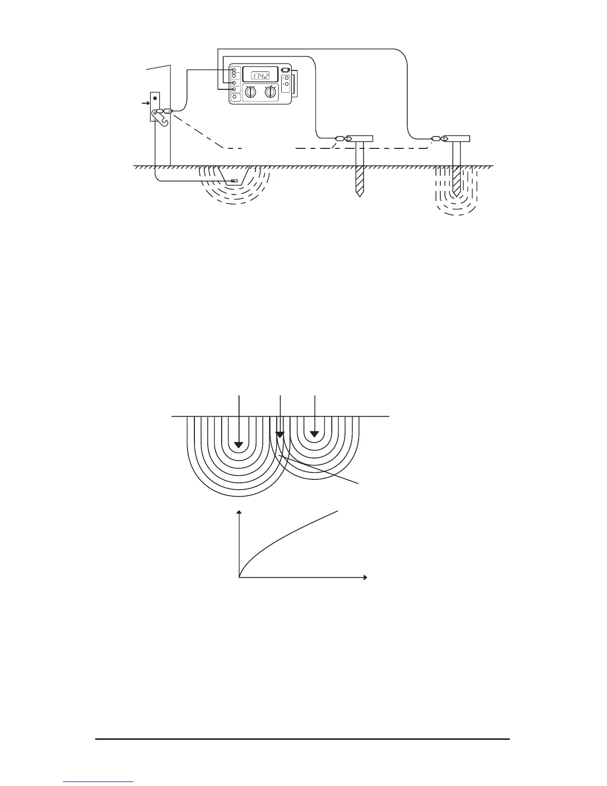
Consider Figure 13, which shows the effective resistance areas
(concentricshells)ofthegroundelectrodeXandoftheauxiliarycurrent
electrode Z. The resistance areas overlap. If readings were taken by
moving the auxiliary potential electrode Y towards either X or Z, the
reading differentials would be great and one could not obtain a reading
within a reasonable band of tolerance. The sensitive areas overlap and act
constantly to increase resistance as Y is moved away from X.
Current
Electrode
Figure 13
Now consider Figure 14, where the X and Z electrodes are sufciently
spaced so that the areas of effective resistance do not overlap. If we plot
theresistance,measuredwendthatthemeasurementsleveloffwhen
Y is placed at 62% of the distance from X to Z, and that the readings on