INSTALLATION
2-2
2.3 INSTALLATION
The unit must be installed with the prescribed
clearances for service as shown in Figure 2.1.
The minimum
clearance dimensions, required by
AERCO, are listed below. Local building codes
may require additional clearance and take
precedence
Minimum clearances required:
Sides 24"
Front 24"
Rear 36"
Top 18"
All gas piping, water piping and electrical conduit
or cable must be arranged so that they do not
interfere with the removal of any cover, or inhibit
service or maintenance of the unit.
WARNING!
KEEP UNIT AREA CLEAR AND FREE
FROM COMBUSTIBLE MATERIALS AND
FLAMMABLE VAPORS AND LIQUIDS.
CAUTION!
While packaged on the shipping skid the
boiler must be moved by pallet jack or
forklift from the rear only.
MASSACHUSETTS INSTALLATIONS
For installations within the Commonwealth
of Massachusetts, the boiler must be
installed by a plumber or gas fitter who is
licensed within the Commonwealth.
In addition, the installation must comply with
all requirements specified in Chapter 1
(Safety Precautions), pages 1-2 and 1-3.
2.3.1. SETTING THE UNIT
The unit must be installed on a 4 to 6 inch
housekeeping pad for proper condensate
drainage. If anchoring the unit, see the
dimensional drawings in Appendix F for anchor
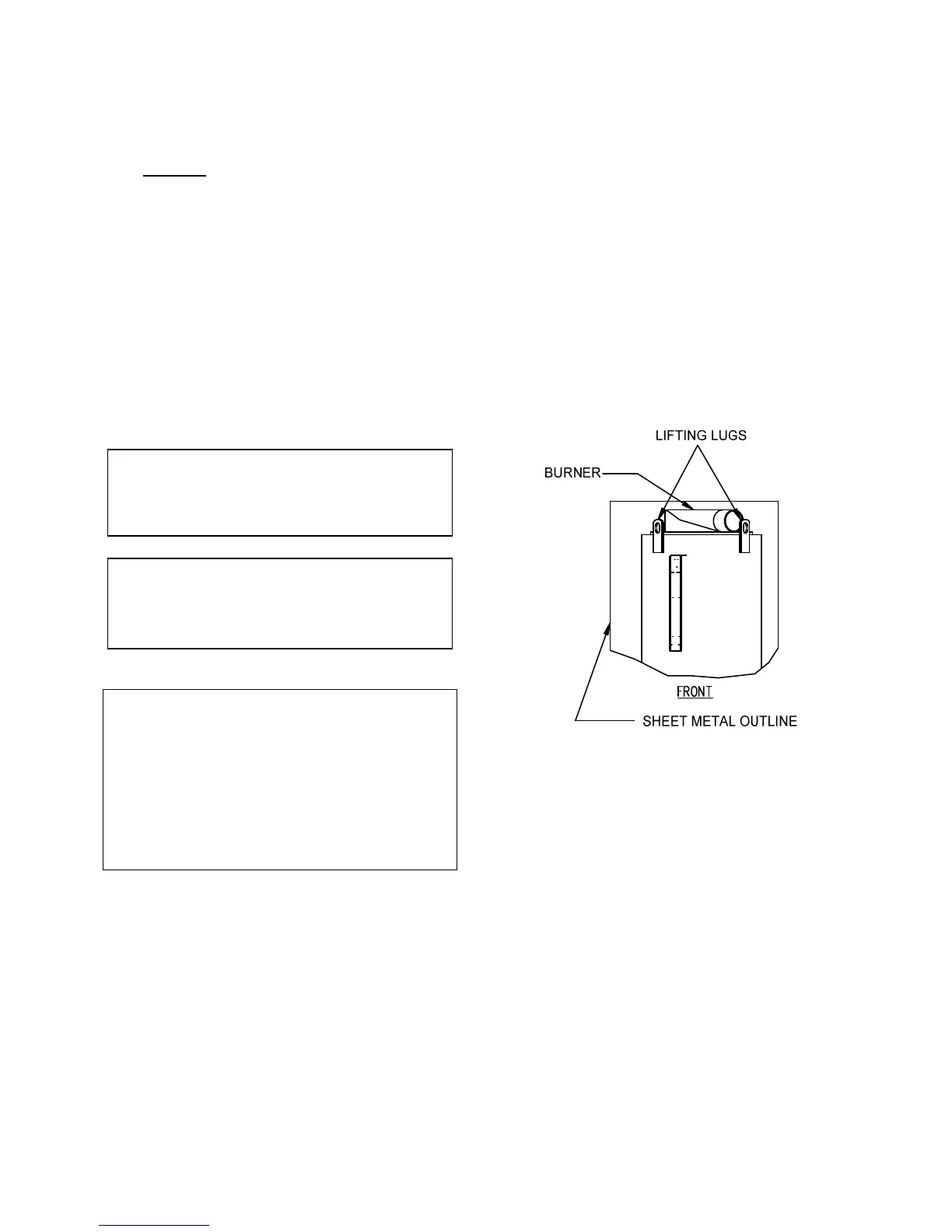
location. Lifting lugs are provided for moving the
unit when it has been removed from the shipping
skid (See Fig. 2.2). USE ONLY THE LIFTING
LUGS TO MOVE THE UNIT. Remove the rear
top panel from the unit to provide access to the
lifting lugs. Remove the four (4) lag screws
securing the boiler to the shipping skid.
Lift the unit off the shipping skid and position it
on to the 4 to 6 inch housekeeping concrete pad
(required) in the desired location.
In multiple unit installations, it is important to
plan the position of each unit. Sufficient space
for piping connections and future maintenance
requirements must be given. All piping must
include ample provision for expansion.
If installing a Combination Control (CCP)
system, it is important to identify and place the
Combination Mode units in the proper physical
location. If these boilers are not properly located,
it will be necessary to reprogram them.
Figure 2.2
Lifting Lug Location
2.3.2 SUPPLY AND RETURN PIPING
The Benchmark 2.0 utilizes 4" 150# flanges for
the water system supply and return piping
connections. See appendix F for dimensional
data. The physical location of the supply and
return piping connections is on the rear of the
unit (See Fig 2.3 For Details).
 Loading...