INITIAL START-UP
4-6
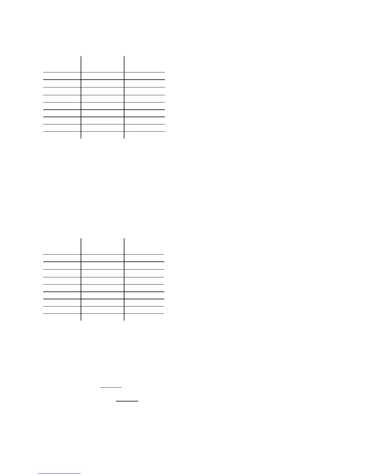
Table 5
Combustion Oxygen Levels for a 24%
Firing Rate
Inlet Air
Temp
Oxygen
Carbon
Monoxide
100°F 12% or less <200 ppm
80°F
12% or less <200 ppm
70°F
12% or less <200 ppm
60
o
F 12% or less <200 ppm
50
o
F 12% or less <200 ppm
40
o
F 12% or less <200 ppm
20
o
F 12% or less <200 ppm
0
o
F 12% or less <200 ppm
-20
o
F 12% or less <200 ppm
14. Raise the firing rate to 100%. Gas pressure
should still be 7.0” for FM gas trains and
7.4” W.C. for IRI gas trains. If it is not,
adjust as necessary
15. Allow the combustion analyzer to settle.
Compare the measured oxygen level with
the levels in Table 6.
Table 6
Combustion Oxygen Levels for 100%
Firing Rate
Inlet Air
Temp
Oxygen
(±0.2)
Carbon
Monoxide
100°F 5.0% <200 ppm
80°F
5.2% <200 ppm
70°F
5.4% <200 ppm
60
o
F 5.5% <200 ppm
50
o
F 5.6% <200 ppm
40
o
F 5.7% <200 ppm
20
o
F 6.0% <200 ppm
0
o
F 6.2% <200 ppm
-20
o
F 6.5% <200 ppm
16. If the measured oxygen reading is within
the specified level in Table 6, no further
adjustment is necessary.
17. If the measured oxygen level is not within
the range specified in Table 6, adjust the
propane supply regulator until the
measured oxygen reading is within
specification. Do Not
change the gas
supply pressure more than ±1.0” W.C. from
its current setting. Do Not
adjust the
differential regulator when firing at a 100%
firing rate.
18. Change the firing rate back to 40%. Allow
time for the combustion analyzer to settle.
Check the measured oxygen reading to
insure that it is still within the range
specified in Table 4.
19. Continue this procedure until oxygen levels
at 40%, 24% and 100% firing rates are
within the ranges specified in Tables 4, 5,
and 6.
20. Set the ON/OFF switch to the OFF position.
21. If the unit will be placed into service using
propane, disregard the following steps and
proceed to paragraph 4.5.
22. If the unit will be placed into service using
natural gas, return the Start and Stop levels
to 20% and 16% (see Appendix K).
23. For natural gas service use, set the diverter
valve handle to the natural gas (horizontal)
position. Close the propane supply valve(s)
to the unit and open the natural gas supply
valve(s).
4.5 UNIT REASSEMBLY
Once combustion calibration is set properly, the
unit can be re-assembled for permanent
operation.
1. Set the green ON/OFF switch to the off
position. Disconnect the AC power supply to
the unit.
2. Shut off the gas supply to the unit.
3. Remove any regulator adjustment tools by
first pulling up the screwdriver blade to
disengage it from the regulator adjusting
screw, and then turning the tool out of the
top of the regulator.
4. Apply a drop of silicone adhesive to the
regulator adjusting screw to lock its setting.
5. Remove the gasket from the tool and place it
back onto the regulator cap.
6. Reinstall the cap and gasket back on the
regulator. Tighten the cap using a
screwdriver or wrench.
7. Remove all of the manometers and barbed
fittings and reinstall the pipe plugs using a
suitable thread compound.
8. Remove the combustion analyzer probe
from the vent hole. Seal the probe hole and
replace the vent connection cover.
9. Replace the unit’s panels.
 Loading...